Instrument layout – KYORITSU 8113 User Manual
Page 8
― 6 ―
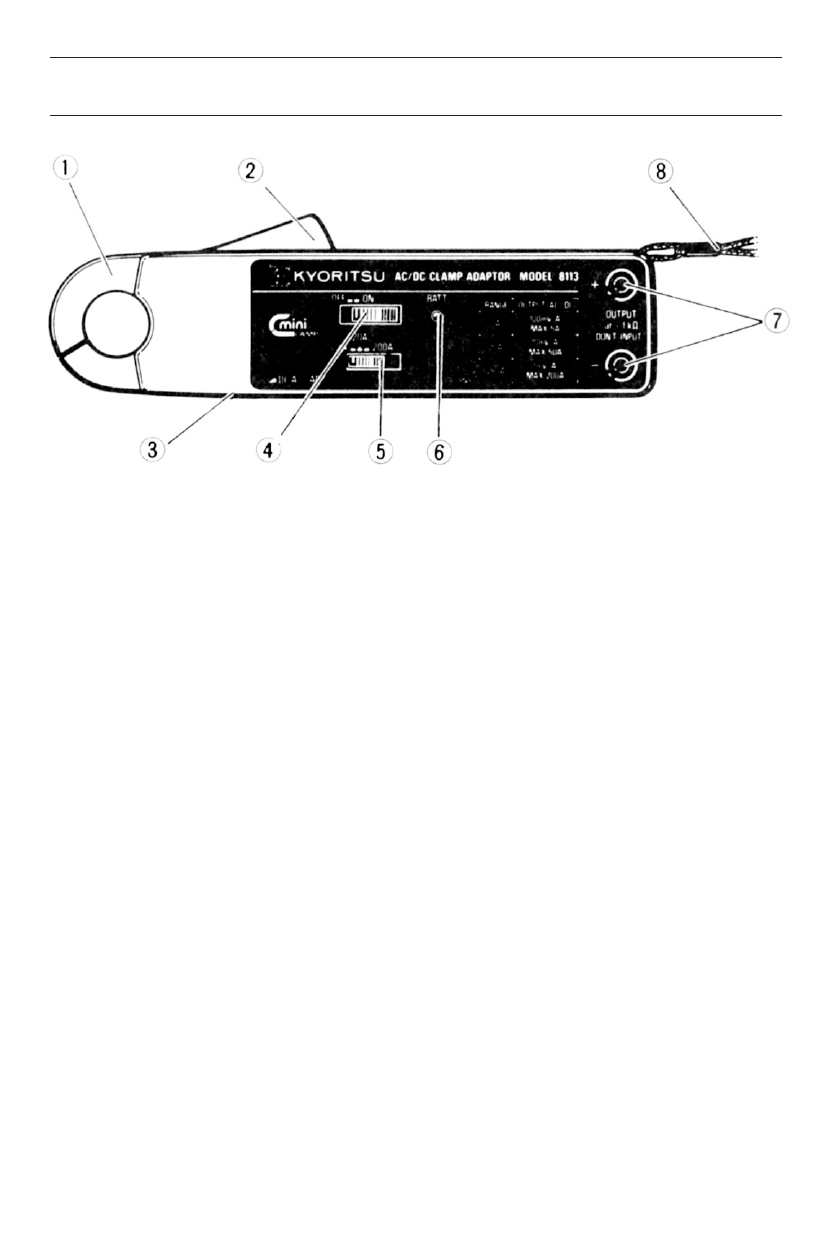
4. Instrument Layout
1 Transformer Jaws
Pick up current flowing through the conductor.
2 Jaw Trigger
Operates the transformer jaws. Press to open the jaws.
3 DC Zero Adj. Knob
Zero adjusts on DC current ranges.
4 Power Switch
Turns power on and off.
5 Range Selector Switch
Selects 2A, 20A or 200A range position.
6 Battery Indicator
LED starts flashing when the power switch is turned on. It
flashes at a longer interval when the battery voltage becomes
exhausted and finally stops flashing at approx. 2.2V. Also,
serves as a power on and low battery indicator.
7 Output Terminals
Output voltage proportional to input current is available from
these terminals.
8 Hand Strap
Prevents the instrument from slipping off the hand during use.
See also other documents in the category KYORITSU Tools:
- 1009 (13 pages)
- 1011 (12 pages)
- 1012 (12 pages)
- 1018 (1 page)
- 1030 (1 page)
- 1061 (58 pages)
- 1051 (40 pages)
- 1109S (36 pages)
- 1110 (1 page)
- 2000 (1 page)
- 2002PA (27 pages)
- 2007A (1 page)
- 2009R (33 pages)
- 2012R (2 pages)
- 2017 (1 page)
- 2031 (1 page)
- 2033 (9 pages)
- 2040 (2 pages)
- 2046R (2 pages)
- 2200 (3 pages)
- 2210R (1 page)
- 2300R (1 page)
- 2413F (24 pages)
- 2413R (24 pages)
- 2431 (2 pages)
- 2432 (1 page)
- 2433R (1 page)
- 2434 (10 pages)
- 2500 (1 page)
- 2608A (2 pages)
- 3005A (24 pages)
- 3021 (24 pages)
- 3121A (12 pages)
- 3126 (28 pages)
- 3127 (60 pages)
- 3128 (88 pages)
- 3131A (20 pages)
- 3132A (20 pages)
- 3161A (24 pages)
- 3321A (24 pages)
- 4105A (10 pages)
- 4106 (48 pages)
- 4116A (20 pages)
- 4140 (32 pages)
- 4200 (24 pages)