KYORITSU 8148 User Manual
KYORITSU Tools
INSTRUCTION MANUAL
KEW 8146/8147/8148
LEAKAGE CLAMP SENSOR
Series
KYORITSU ELECTRICAL INSTRUMENTS WORKS, LTD.,
TOKYO, JAPAN
KEW8146
KEW8147
KEW8148
LEAKAGE CLAMP SENSOR
1. Safety warnings
This instrument has been designed, manufactured and
tested according to IEC 61010: Safety requirements for
Electronic Measuring apparatus, and delivered in the
best condition after passing quality control tests. This
instruction manual contains warnings and safety rules
which have to be observed by the user to ensure safe
operation of the instrument and to maintain it in safe
condition. Therefore, read through these operating
instructions before using the instrument.
WARNING
● Read through and understand instructions contained
in this manual before using the instrument.
● Keep the manual at hand to enable quick reference
whenever necessary.
● The instrument is to be used only in its intended
applications.
The operating instructions described in the manual
must be observed.
● Understand and follow all the safety instructions
contained in the manual.
It is essential that the above instructions are adhered
to. Failure to follow the above instructions may cause
injury and or instrument damage.
The symbol indicated on the instrument, means that
the user must refer to the related parts in the manual
for safe operation of the instrument. It is essential to
read the instructions wherever the symbol appears
in the manual.
DANGER is reserved for conditions and actions that
are likely to cause serious or fatal injury.
WARNING is reserved for conditions and actions
that can cause serious or fatal Injury.
CAUTION is reserved for conditions and actions that
can cause minor injury or instrument damage.
DANGER
● Never make measurement on a circuit in which the
electrical potential exceeds AC300V.
● Do not make measurement when thunder rumbling. If the
instrument is in use, stop the measurement immediately
and remove the instrument from the measured object.
● Do not attempt to make measurement in the presence of
flammable gasses. Otherwise, the use of the instrument
may cause sparking, which can lead to an explosion.
● The transformer jaws are made of metal and their tips
are not completely insulated. Be especially careful
about the possible shorting where the measured
object has exposed metal parts.
● Never attempt to use the instrument if it's surface or
your hand are wet.
● Do not exceed the maximum allowable input of any
measuring range.
WARNING
● Never attempt to make any measurement, if any
abnormal conditions are noted, such as broken case,
and exposed metal parts.
● Do not install substitute parts or make any
modification to the instrument.
Return the instrument to the distributor from who you
purchased this instrument for repair or re-calibration in
case of suspected faulty operation.
● Always keep your fingers and hands behind the barrier
on the instrument to avoid the possible shock hazard.
CAUTION
● Do not step on or pinch the cord to prevent the jacket
of cord from being damaged.
● The output connector shall be removed or connected
without clamping a conductor. Otherwise, it may cause
a failure.
● Do not expose the instrument to direct sunlight, high
temperatures, humidity or dew.
● Never give shocks, such as vibration or drop, which
may damage the instrument.
● Use a damp cloth and detergent for cleaning the
instrument. Do not use abrasives or solvents.
Safety symbols
F
∼
Refer to the instructions in the manual.
Indicates a Instrument with double or reinforced insulation
Indicates that this instrument can clamp on live bare
conductors when the voltage to be tested is below
Circuit - Ground-to-Earth voltage against the indicated
Measurement Category.
Indicates AC
Transformer
Interior wiring
Incoming wire
CAT.Ⅳ
CAT.Ⅰ
CAT.Ⅱ
CAT.Ⅲ
Socket
○Measurement categories(Over-voltage categories) To
ensure safe operation of measuring instruments, IEC
61010 establishes safety standards for various electrical
environments, categorized as CATⅠto CATⅢ, and called
measurement categories.
Higher-numbered categories correspond to electrical
environments with greater momentary energy, so a
measuring instrument designed for CATⅢ environments
can endure greater momentary 0energy than one
designed for CATⅡ.
CATⅠ: Secondary electrical circuits connected to an AC
electrical outlet through a transformer or similar
device.
CATⅡ: Primary electrical circuits of equipment connected
to an AC electrical outlet by a power cord.
CATⅢ: Primary electrical circuits of the equipment
connected directly to the distribution panel, and
feeders from the distribution panel to outlets.
CATⅣ: The circuit from the service drop to the service
entrance, and to the power meter and primary
overcurrent protection device (distribution panel).
2. Features
● Clamp sensor for AC leakage current measurement.
● Can measure up to:
KEW 8146:30A
KEW 8147:70A
KEW 8148:100A
● Designed to international safety standard IEC61010-2-032
CAT. Ⅲ Pollution Degree 2
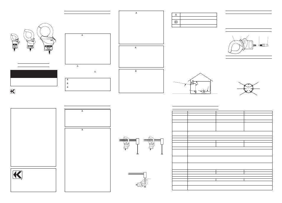
3. Instrument layout
4. DIN Plug pin assignment
3: GND pin
5: Output signal pin
6: Sensor Signal pin
(Resistance between 3Pin and 6Pin:
8146:47kΩ 8147:8.2kΩ 8148:30kΩ)
1, 2 and 4: No use
*Lower figure shows the pin assignment seeing the Clamp
sensor from output connector part. The figure of the pin
assignment of connection terminal is symmetrical to lower
figure.
5
3
1
2
4
6
Transform Jaws
Trigger
Cable
Output connector
Barrier
92―1746A
05-10
DISTRIBUTOR
KYORITSU ELECTRICAL
INSTRUMENTS
WORKS, LTD.
No.5-20, Nakane 2― chome, Meguro-ku,
Tokyo, 152-0031 Japan
Phone:81-3-3723-0131 Fax:81-3-3723-0152
URL:http://www.kew-ltd.co.jp
E-mail:[email protected]
Factories:Uwajima&Ehime
5. Operating instructions
DANGER
● Never make measurement on a circuit in which the
electrical potential exceeds AC300V in order to avoid
possible shock hazard.
● The transformer jaws are made of metal and their tips
are not completely insulated. Be especially careful
about the possible shorting where the measured
object has exposed metal parts.
.
CAUTION
● Take sufficient care to avoid shock, vibration or
excessive force when handling the instrument.
Otherwise, precisely adjusted transformer jaws will be
damaged.
●When transformer jaws do not fully close, never try to
close them by force, but make them free to move and
try again. If a foreign substance is stuck in the jaw tips,
remove it.
● When making current measurements, keep the
transformer jaws fully closed.
Otherwise, accurate measurements cannot be taken.
● Hold the inserting part (except for the cable) and
disconnect the Output connector from the measuring
instrument so as not to cause a break in the cord.
● When measuring current which pulse element is
superposed, differences of the indicated value may
be caused between ranges, if the peak value exceeds
the measurement range to a large extent. In this
case, the reading at the bigger range should be taken
as a right value. Sensitive transformer jaws are used
for Leakage clamp meter. Because of the
characteristics of transformer jaws, which can be
opened and closed, it is impossible to eliminate the
interference of external magnetic field completely. If
there is a presence of strong magnetic field, use the
instrument at a distance as far as possible from it.
Following are the typical things generating magnetic
field.
・Conductor fed large current
・Motor
・Equipment which has magnet
・Integrating wattmeter
5-1 Measuring method
(1) Connect the Output connector to the Input terminal of
the measuring instrument.
(2) Press the Trigger to open the transformer jaws and
clamp onto one conductor.
In this case, the measured conductor shall be at the
center of the jaws.
(3) Ensure that the tips of transformer jaws are firmly closed.
5-2 Measuring method
(1) Measuring out of balance leakage current (See
Fig.1):Clamp onto all conductors except a grounded
wire.
(2) Measuring earth leakage current (See Fig.2):Clamp
onto a grounded wire.
3- phase 3- wire system
(In 4- wire system with neutral,
clamp onto all 4 wires)
Fig.1 Measuring out of balance leakage current
Grounded wire
Load
Load
Load
Single- phase 2- wire system
(In 3- wire system with neutral,
clamp onto all 3 wires)
Fig.2 Measuring earth leakage current
MINI DIN 6PIN
50MΩ or greater at 1000V
between Jaw and enclosure
between enclosure and output terminal
between Jaw and output terminal
Model
Rated voltage
Output voltage
Measuring range
Accuracy
(Input: sine wave)
Temperature & humidity range
(Guaranteed accuracy)
Operating temperature range
Storage temperature range
Maximum permissible input
Output
impedance
Location for use
Applicable
standards
Withstand
voltage
Insulation
resistance
Conductor Size
Dimension
Cable length
Output terminal
Weight
Accessories
Option
6. Specifications
23±5℃, relative humidity: 85% or less (no condensation)
0∼50℃, relative humidity: 85% or less (no condensation)
-20∼60℃, relative humidity: 85% or less (no condensation)
Altitude up to 2000m, Indoors
IEC 61010-1, IEC 61010-2-032
Measurement CAT. Ⅲ (300Vrms)
Pollution degree 2
IEC 61326
Approx. 2m
Instruction manual
Cable marker
Approx. 510g
Approx. 240g
Approx. 150g
186(L)×129(W)×53(D)mm
128(L)×81(W)×36(D)mm
100(L)×60(W)×26(D)mm
Approx.68mm in diameter (max.)
Approx.40mm in diameter (max.)
Approx.24mm in diameter (max.)
AC3540Vrms (50/60Hz)for 5 sec.
between Jaw and enclosure
between enclosure and output terminal
between Jaw and output terminal
Approx. 60Ω
Approx. 100Ω
Approx. 90Ω
AC100Arms continuous (50/60Hz)
AC70Arms continuous (50/60Hz)
AC30Arms continuous(50/60Hz)
0A∼80A
±1.0%rdg±0.1mV (50/60Hz)
±2.0%rdg±0.2mV (40∼1kHz)
80A∼100A
±5.0%rdg (50/60Hz)
±10.0%rdg (45∼1kHz)
0A∼15A
±1.0%rdg±0.1mV (50/60Hz)
±2.0%rdg±0.2mV (40∼1kHz)
15A∼30A
±5.0%rdg(50/60Hz)
±10.0%rdg(45∼1kHz)
0A∼40A
±1.0%rdg±0.1mV (50/60Hz)
±2.0%rdg±0.2mV (40∼1kHz)
40A∼70A
±5.0%rdg (50/60Hz)
±10.0%rdg (45∼1kHz)
AC0∼100A
AC0∼70A
AC0∼30A
AC0∼5000mV
(50mV/A)
AC0∼3500mV
(50mV/A)
AC0∼1500mV
(50mV/A)
AC100Arms(141.4Apeak)
AC70Arms(99.0Apeak)
AC30Arms(42.4Apeak)
KEW 8148
KEW 8147
KEW 8146
MODEL 7146(Banana Φ4 adjuster plug)
MODEL 7185(Extension cable)