KYORITSU 2608A User Manual
Page 2
d. Take the reading on the scale for the
selected range.
e. After completing the measurement,
remove the test leads from the circuit
under test.
a. Set range switch to the “DC
60V”position.
b. Insert the red test lead to the V terminal
and the black test lead to the COM
terminal.
c. Connect the red test lead tip to the
positive side of the circuit under test and
the black test lead tip to the negative
side.
d.Take the reading on the 60V scale.
e. After completing the measurement,
remove the test leads from the circuit
under test.
d. Connect the tip of the test leads to the
circuit under test.
e. Take the reading on the resistance scale
and multiply it as follows.
a. Set the range switch to the “
×
1Ω” or “
×
10Ω” position.
b. Insert the red test lead to the OHM
terminal and the black test lead to the
COM terminal.
c. With the test leads shorted, set the
pointer over the “0” mark at the right end
of the resistance scale, using the OHM
zero adjuster.
9−1 Sending for Repair
Make sure to provide description of the
failure and your name, address and telephone
number. Pack the instrument securely so that
it will not be damaged during transportation
and forward it to your distributor.
9−2 Periodic Calibration
In order to maintain measurement accuracy,
it is recommended that you forward the
instrument to Kyoritsu Repair Center for
calibration once every year.
NOTE:
Calibration is charged.
a. Set the range switch to the “TEMP (
×
10Ω)”
position.
b. Insert the red test lead to the OHM
terminal and the black test lead to the
COM terminal.
c. With the test leads shorted, set the
pointer over the “0” mark at the right end
of the resistance scale, using the OHM
zero adjuster.
d. Remove the test leads from the terminals.
e. Insert Model 7060’s red plug to the OHM
terminal and the black plug to the COM
terminal.
f. Touch the tip of the temperature probe to
the part under test.
g. Wait until the reading become stable,
then take the reading on the temperature
scale.
7−2 Fuse Replacement
The instrument s resistance measuring
circuit is protected by a 0.5A/250V fuse.
When the instrument does not operate
properly in resistance measurement,
check the fuse and replace it in the
following steps, when necessary.
a. Remove the test leads from the
instrument.
b. Remove the screw on the back side of the
bottom case to open the instrument.
c. Replace the blown fuse with the spare
fuse installed beneath the battery.
d. Screw the bottom case back onto the
instrument.
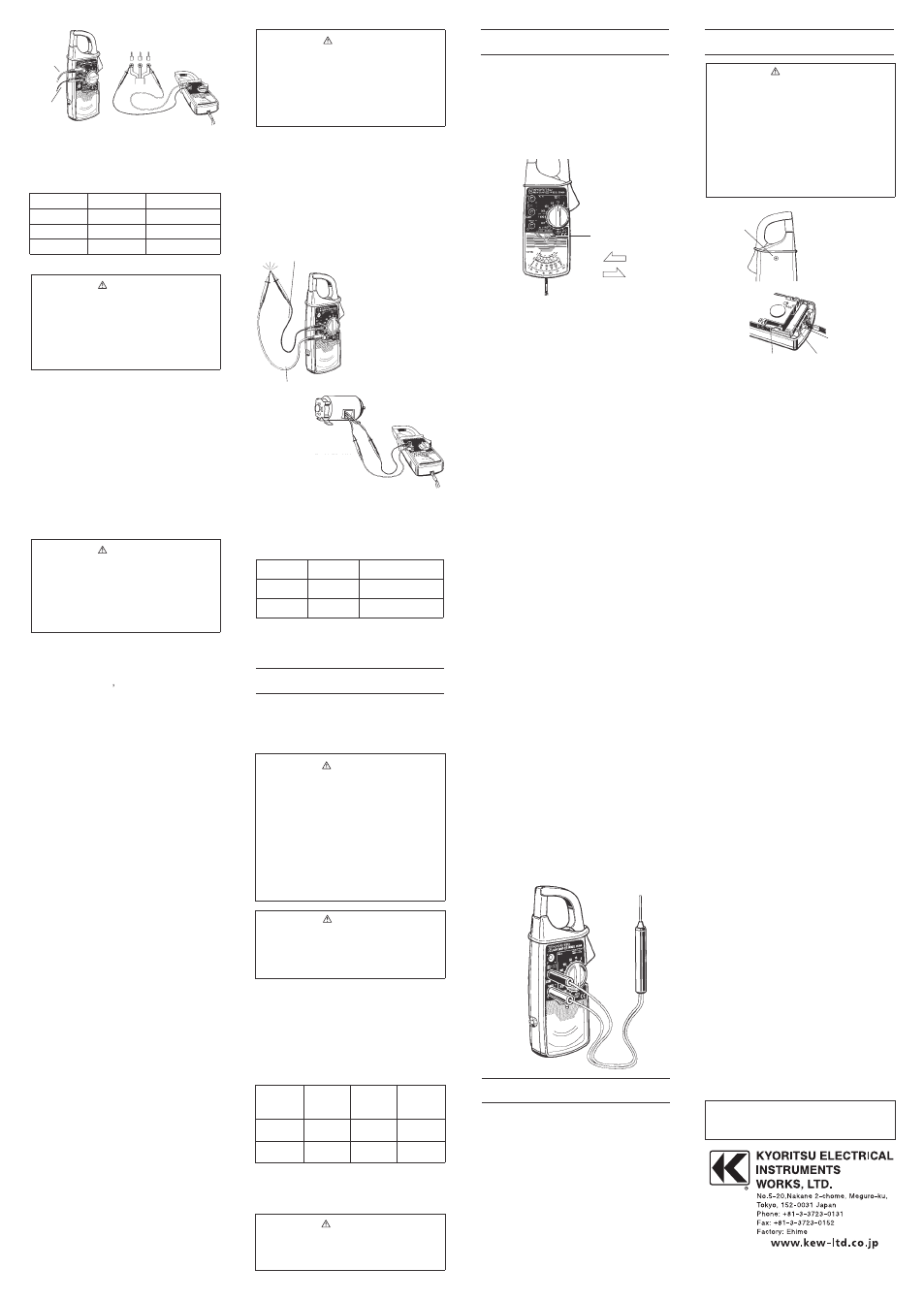
7−1 Battery Replacement
a. Remove the test leads from the
instrument.
b. Remove the screw on the back side of the
bottom case to open the instrument.
c. Replace the battery with a new R6P
battery or equivalent. The new battery
must be installed in the orientation
indicated inside the instrument.
d. Screw the bottom case back onto the
instrument.
The pointer lock feature can be used for
measurement in dimly light or hard-to-read
locations.
a.Make AC current, AC voltage, DC voltage
or resistance measurement as described
in section 5.
b. Slide the pointer lock button to the left
position.
c. Take the reading away from the
conductor or the circuit under test.
d. To release the pointer lock, slide the
button to the right.
Model 7060
Model 7060 is an temperature probe with a
measuring range from −20℃ to +150℃.
a. Set the range switch to the desired position.
b. Clamp Kew Snap 2608A onto the pick-up coil
of Multi-Tran.
c. Clamp Multi-Tran onto the bus-bar or
conductor under test.
d. Take the reading on Kew Snap 2608A and
multiply it by 10.
Model 8004 and 8008 (Multi-Trans)
Multi-Trans extend existing current
measuring range up to 3000A as well as the
maximum conductor size.
保 証 規 定
保証期間中に生じました故障は、以下の場合除き無償で
修理いたします。
1.取扱説明書によらない不適切な取扱い、使用方法、保
管方法が原因で生じた故障
2.お買い上げ後の持ち運びや輸送の間に、落下させるな
ど異常な衝撃が加わって生じた故障
3.当社のサービス担当者以外の改造、修理、オーバーホ
ールが原因で生じた故障
4.火災、地震、水害、公害およびその他の天変地異が原
因で生じた故障
5.傷などの外観上の変化
6.その他当社の責任とみなされない故障
7.電池など消耗品の交換、補充
8.保証書のご提出がない場合
◎ご注意
当社で故障状態の確認をさせていただき、上記に該当
する場合は有償とさせていただきます。
輸送中に損傷が生じないように梱包を施し、当社修理
センターまたは取扱店宛にお送りください。
9.After-sales Service
8. Optional Accessaries
7. Battery and Fuse Replacement
6. Using Pointer Lock
修理内容
担当者
年月日
保証期間 ご購入日( 年 月 日)より1カ年間
製造番号
型名MODEL2608A
LLLLLLLLLLLLLLLLLLLLLLLLLLLLLLLLLLLLLLLLLLLLLLLL
LLLLLLLLLLLLLLLLLLLLLLLLLLLLLLLLLLLLLLLLLLLLLLLL
保証書
04-10
92-1396C
5−3 DC Voltage Measurement
5−4 Resistance Measurement
Model8004
Model8008
Max. conductor
size
(mm in diameter)
φ60
φ100
Measuring
range
AC0∼
1000A
AC0∼
3000A
Input to
output ratio
10:1
10:1
Models
Scale used Multiply reading by
Ω
×1
Ω
Ч10
Ч1Ω
×10Ω
Range
AC150V
AC300V
AC600V
Scale used
150V
300V
60V
Multiply reading by
Ч1
Ч1
Ч10
Range
RED
TEST LEAD
BLACK
TEST LEAD
RED TEST LEAD
BLACK TEST LEAD
POINTER LOCK
BUTTON
LOCK
RELEASE
WARNING
・Do not make measurement on a circuit
above 60V DC.
・Do not make measurement with the
bottom case removed.
・Keep your fingers and hands behind the
barrier during measurement.
WARNING
・To avoid electric shock hazard, make
sure to remove the test leads from the
instrument before trying to replace
batteries.
・Make sure to screw the bottom case
back onto the instrument after battery
or fuse replamement.
・Do not install a battery or fuse that does
not have the specified rating.
WARNING
・Do not make measurement with the
bottom case removed.
・Make sure that there is no voltage in
the circuit or equipment under test.
・Keep your fingers and hands behind the
barrier during measurement.
CAUTION
・Make sure to remove the test leads
from the terminals when resistance
measurement is over. If the test leads
are left inserted to the terminals, their
inadvertent shorting can exhaust the
battery.
WARNING
・Do not make measurement on a circuit
above 600V AC.
・The transformer jaws are made of metal
and their tips are not insulated. Never
touch the exposed metal parts under
test with jaw tips.
・Do not make measurement with the
bottom case removed.
・Do not make measurement with the test
leads connected to the instrument.
CAUTION
・When the order of the current under
test is not known, make measurement
first on the highest 300A range, then
switch to the appropriate range.
WARNING
Do not make measurement on a metal part
with a voltage more than 30V AC or 60V
DC.
SCREW
FUSE
R6P BATTERY
SPARE FUSE
KYORITSU ELECTRICAL
INSTRUMENTS
WORKS, LTD.
No.5-20,Nakane 2-chome, Meguro-ku,
Tokyo, 152-0031 Japan
Phone : 81-3-3723-0131
Fax : 81-3-3723-0152
URL : http://www.kew-Itd.co.jp
E-mail : [email protected]
Factories : Uwajima & Ehime
KYORITSU reserves the rights to change
specifications or designs described in this
manual without notice and without obligations.
9-09
600V
92-1396D