KYORITSU 2056R User Manual
Page 2
■
Press the MIN/MAX Key to select MAX or MIN. The
max or min value within measuring range is being
held until this function is disabled. "MIN" or "MAX" is
indicated on the display while this function is being
activated. To disable this function, press down the
MIN/MAX Key at least 2 sec or change functions.
(2)
AC/DC Voltage Range
CAUTION
Pressing the MIN/MAX Key without applying voltage
disables the Auto-ranging function and fixes the
Range to 6V. Connect the test leads to the circuit
under test and press the MIN/MAX Key after an
appropriate range is selected by Auto-ranging function.
Pressing the MIN/MAX Key enables min or max
value measurement. Press the MIN/MAX Key to
select MAX or MIN. The max or min value within
measuring range is being held until this function is
disabled. "MIN" or "MAX" is indicated on the display
while this function is being activated. To disable this
function, press down the MIN/MAX Key at least 2
sec or change functions.
6-5. ZERO Function
CAUTION
MIN/MAX, PEAK keys are disabled while ZERO
Function is being activated.
Zero Adjustment Function at Current Range "
△"
mark is to be indicated at the upper right on the
display while ZERO function is being operated.
Indication of relative value at current, voltage,
resistance:
Pressing the ZERO Key indicates REL (relative
value) Press the ZERO Key to save the initial value
at the start of measurement as a reference value.
Then the difference between the later measured
values and the reference value is indicated on the
display. The Auto-ranging function is disabled, while
this function is being activated, and the Range is
fixed to the Range selected at the start of
measurement. Relative value is indicated within
following ranges.
(Measuring range) =
(Full-scale value at the fixed Range) - (Initial value)
To disable this function, press down the MIN/MAX
Key at least 2 sec or change functions.
6-6. PEAK Function (600A only on KEW2046R)
(1) Set the Function Switch to "
AC Current" position
and clamp onto a conductor under test.
(2) Pressing the PEAK Key indicates "
P
MAX" on the
display and initiates measurement.
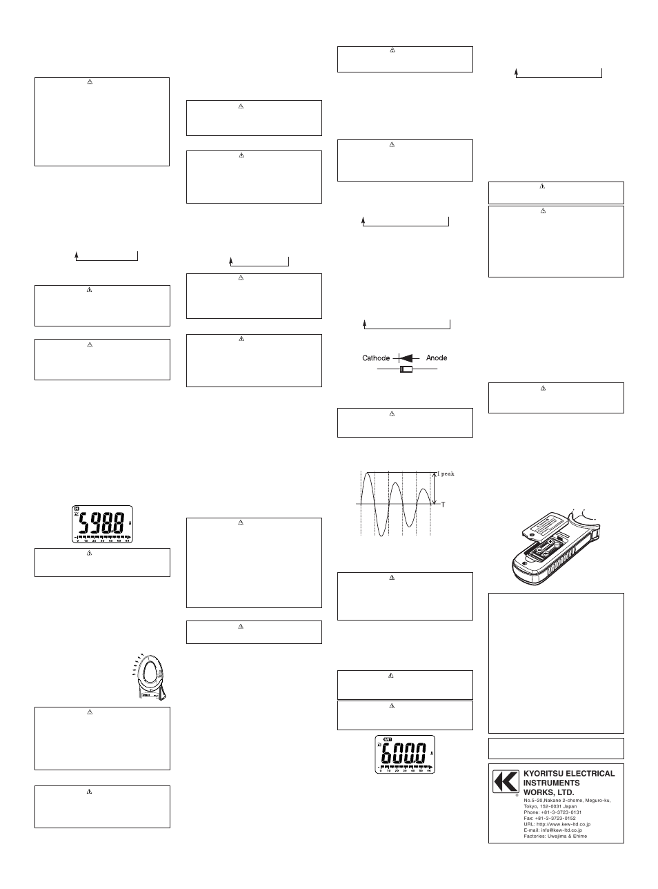
(3) Readings indicates the PEAK of current crest
value. When measuring sine wave, reading is
about
√2 times of RMS value.
measurement mode,and the Data hold function is
disabled. Otherwise,desired measurement cannot be
made.
5. Measurement
5-1. AC Current Measurement
DANGER
●
Never make measurement on a circuit in which
voltage over AC600V exists to avoid getting
electrical shock.
●
Transformer jaw tips are designed not to short the
circuit under test. If equipment under test has
exposed conductive parts, however, extra pre-
caution should be taken to minimize the possibility
of shorting.
●
Do not make measurement with the Battery Cover
removed.
●
Disconnect the test leads from the instrument for
current measurement.
(1) Set the Function Switch to "600A" or "1000A"
position.
(on KEW2046R, only "600A" is available) AC has
been selected by default; press the SELECT key,
when DC has been selected, to change it to AC.
AC mark is displayed at the upper left on the
display.
(2) Press the trigger to open the transformer jaws and
clamp them onto the one conductor under test,
then take the reading on the display. Pressing the
"
Hz/DUTY" Key switches the indication in following
sequence.
AC Current e
Hz e
DUTY
Hz/DUTY Function requires 50A or more at AC600A
Range and 350A or more at AC1000A range.
CAUTION
●
Max conductor size for KEW2046R is approx dia.
33mm and for KEW2056R is approx dia. 40mm.
During current measurement, keep the
transformer jaws fully closed. Other wise, accurate
measurements cannot be taken.
5-2. DC Current Measurement
DANGER
●
Never make measurement on a circuit in which
voltage over DC600V exists to avoid getting
electrical shock.
●
Do not make measurement with the Battery Cover
removed.
(1) Set the Function Switch to "
600A" or "1000A"
position. AC has been selected by default; press
the SELECT key, when AC has been selected, to
change it to DC. (only 600A is available on
KEW2046R) DC mark is displayed at the upper left
on the display.
(2) With the transformer jaws closed and without
clamping them onto the conductor, press the
"
ZERO" key to zero adjust the display. (△mark is
displayed at the upper right on the display.)
(3) Press the trigger to open the transformer jaws and
clamp them onto the one conductor under test, the
conductor should be at the center of the jaws, then
take the reading on the display.
(4) Set the Function Switch to an appropriate
position according to current under test.
(5) Pressing the "
ZERO" key again releases "ZERO"
function. (△mark at the upper right on the display
disappears.)
CAUTION
●
When the current flows from the upside (the
display side) to the underside of the instrument,
the polarity of the reading is positive and vice
versa.
5-3. AC Voltage Measurement
DANGER
●
Never make measurement on a circuit in which
voltage over AC600V exists to avoid getting
electrical shock.
●
Do not make measurement with the Battery Cover
removed.
●
Keep your fingers behind the barrier on the
instrument during measurement.
(1) Set the Function Switch to "
ACV" position.
(2) Connect the red test lead to V/
Ω terminal and the
black test lead to COM terminal.
(3) Connect the test leads to the circuit under test. Take
the reading on the display. Pressing the "
Hz/DUTY"
key while reading is indicated on the display
switches the indication in following sequence.
AC Voltage e Hz e DUTY
CAUTION
●
Hz/DUTY Function requires AC40V or higher.
●
To measure a frequency, measure the voltage on
the electrical circuit in advance. Then press the
Hz/DUTY key to enter into frequency measurement.
●
Readings of frequency may fluctuate or be
influenced under noisy environment.
5-4. DC Voltage Measurement
DANGER
●
Never make measurement on a circuit in which
voltage over DC600V exists to avoid getting
electrical shock.
●
Do not make measurement with the Battery Cover
removed.
●
Keep your fingers behind the barrier on the
instrument during measurement.
(1) Set the Function Switch to "
DCV" position.
(2) Connect the red test lead to V/
Ω terminal and the
black test lead to COM terminal.
(3) Connect the red and black test leads to the
positive (+) and negative (-) sides of the circuit
under test respectively. Take the reading on the
display. If the connection is reversed, the display
indicates the "-" mark.
5-5. Resistance/ Diode/ Cont/ Capacity Measurement
DANGER
●
Never use the instrument on an energized circuit.
●
Do not make measurement with the Battery Cover
removed.
Resistance
(1) Set the Function Switch to "
Ω/Diode/Cont/Capacity"
position.
(2) Connect the red test lead to V/
Ω terminal and the
black test lead to COM terminal. Confirm "OL" is
indicated on the display, and then short-circuit the
tips of test leads to make the indication zero.
(3) Connect the test leads to the both ends of the
resistor under test.
(4) Take the reading on the display.
CAUTION
●
Even if short the test lead tips, indicated value
may not be zero. But this is because of the
resistance of test leads and not a failure.
●
When test leads are open, "OL" is indicated on the
display.
Continuity
(1) Set the Function Switch to "
Ω/Diode/Cont/Capacity"
position. "
Ω" has been selected by default; press the
SELECT key to change it to "
Continuity"
Resistance e Diode e Cont e Capacity
(2) Connect the red test lead to V/
Ω terminal and the
black test lead to COM terminal. Confirm "OL" is
indicated on the display and short circuit the tips of
test leads. Indication should become zero and
buzzer sounds.
(3) Connect the test leads to the both ends of the
conductor under test. The buzzer sounds, if the
resistance under test is 100
Ω or less.
Diode
(1) Set the Function Switch to "
Ω/Diode/Cont/Capacity"
position. "
Ω" has been selected by default; press the
SELECT key to change it to "
Diode"
Resistance e Diode e Cont e Capacity
(2) Connect the red test lead to V/
Ω terminal and the
black test lead to COM terminal.
(3) Connect the red and black test leads to the Anode
and Cathode of the diode under test respectively.
Take the reading on the display. If the connection
is reversed, the display indicates "
OL".
CAUTION
●
Some of diodes cannot be tested. Indication on
the display will be "OL".
(Zener diode, LED and so on)
Capacity
(1) Set the Function Switch to "
Ω/Diode/Cont/Capacity"
position. "
Ω" has been selected by default; press the
SELECT key to change it to "
Capacity"
Resistance e Diode e Cont e Capacity
(2) Connect the red test lead to V/
Ω terminal and the
black test lead to COM terminal.
(3) Connect the test leads to the both ends of the
capacitor under test.
(4) Take the reading on the display.
5-6 Temperature Measurement
(1) Set the Function Switch to "
°
C/
°
F" position.
(2) Connect the K-type Temperature Probe (Optional
Accessories) to the input terminal. Positive (+) side
of Probe should be connected to V/
Ω.
(3) Contact the Sensor (metal part) of K-type
Temperature Probe to the object under test. Take
the reading on the display. Positive (+) side of
Probe should be connected to V/
Ω.
WARNING
●
Never connect the Temperature Probe to an
energized circuit.
CAUTION
●
Room temperature is indicated on the LCD when
setting the Function Switch to "
°
C/
°
F" position. In
case that "OL" or anything other than room
temperature is indicated, something may wrong
with the instrument. Stop the use of instrument
immediately.
●
There may be a break in Probe when indication
isn't changed if Sensor (metal part) of K-type
Temperature Probe is contacted with the object
under test.
6. Other functions
6-1. Sleep Function
(1) This is a function to prevent the instrument from
being left powered on in order to conserve battery
life. This function causes the instrument to enter
Sleep mode about 15 minutes after the last key
operation. To exit the Sleep mode, turn the
Function switch to "OFF", then to any other
position.
(2) Sleep Function is disabled when;
MIN/MAX or PEAK Function is selected.
Continuous measurement is made with the Sleep
Function being disabled. To activate Sleep
Function again, disable the MIN/MAX or PEAK
Function.
CAUTION
●
The instrument consumes small amount of battery
power in the Sleep mode. Set the Function Switch
to the OFF position after use.
6-2. HOLD Key
(1) Data Hold Function
This is a function to freeze the measured value on
the display. Press the "HOLD" key to freeze the
reading.
The reading will be held regardless of subsequent
variation in input. "H" is indicated on the upper left
corner of the display while the instrument is in the
Data Hold mode. To exit Data Hold mode, press
the "HOLD" key again.
CAUTION
●
Held readings are released when Sleep Function
is activated while the instrument is in the Data
Hold mode.
(2) Backlight ON/OFF
Pressing the HOLD key 2 sec or more lights up the
Backlight. Pressing the HOLD key 2 sec or more
again turns off the Backlight.
6-3. NCV Function
Red LED on the upper area on the Panel lights up at
All functions except for OFF when electric field
exceeding 100V is detected by the sensor installed
in the Jaws.
It indicates a presence of voltage in an electrical
circuit or equipment without
touching them.
NCV Sensor can detect electrical
field only from the direction
indicated in the right figure.
Put the fixed element (left side)
closer to the conductor under test.
Detection against in-wall outlet is
impossible.
DANGER
●
The LED may not light up due to installation
condition of electrical circuit or equipment. Never
touch the circuit under test to avoid possible
danger even if the LED for NCV doesn't light up.
●
Check the functionality of LED on a well-known
power supply prior to measurement. When the
LED doesn't light up, do not make measurement.
●
NCV indication is affected by external voltage,
how to hold or place the instrument.
6-4. MIN/MAX Function
CAUTION
●
Held readings are released when Sleep Function
is activated while the instrument is in the Data
Hold mode.
●
SELECT, ZERO, Hz/DUTY keys are disabled
while MIN/MAX Function is being activated.
(1)
AC/DC Current Range (600A only on KEW2046R)
Pressing the MIN/MAX Key at 600A & 1000A
Function enables min or max value measurement.
(4) Press the PEAK Key at least 2 sec to reset the
indication or release PEAK Function.
Buzzer sounds twice, and the Function is
released.
CAUTION
●
PEAK indication for Crest value is up to 1500A.
Error indication is given when exceeding this
range value.
●
Sleep Function is disabled when PEAK Function is
selected. Care should be taken when performing
continuous measurement.
6-7. Over-flow indication
When the input exceeds the measuring range at
each Function other than Voltage ,1000A and
Temperature Range "OL" or "-OL" is indicated on the
display.
7. Battery Replacement
WARNING
●
To avoid electrical hazard, set the Function Switch
to "OFF" and remove the test leads from the
instrument before trying to replace batteries.
CAUTION
●
Do not mix old and new batteries.
●
Install batteries in correct polarity as indicated in
the Battery Compartment.
Replace the batteries when a Low Battery Voltage
warning "
BATT" mark is indicated on the display.
Note that when the battery is completely exhausted,
the display blanks without "
BATT" mark shown.
(1) Set the Function Switch to "OFF" position.
(2) Unscrew and remove the Battery Compartment
Cover on the bottom of the instrument.
(3) Replace the batteries observing correct polarity.
Use new R03 (AAA) or LR03 / 1.5V batteries.
(4) Install the Battery Compartment and tighten the
screws.
8. Maintenance
●
Cleaning
Use a cloth dipped in water or neutral detergent for
cleaning the instrument.
Do not use abrasives or solvents. Otherwise,
instrument get damaged, deformed or discolored.
DISTRIBUTOR
Kyoritsu reserves the rights to change
specifications or designs described in this manual
without notice and without obligations.
05-12
92-1803