Electrical connection, 1 potential equalization – KROHNE UFM 500 ATEX EN User Manual
Page 5
4
2. ELECTRICAL CONNECTION
NOTE:
All the connecting cables that enter the terminal compartment of the UFC 500-EEx
signal converter (i.e. power supply, current and binary in-/outputs cables) are not
intrinsically safe !
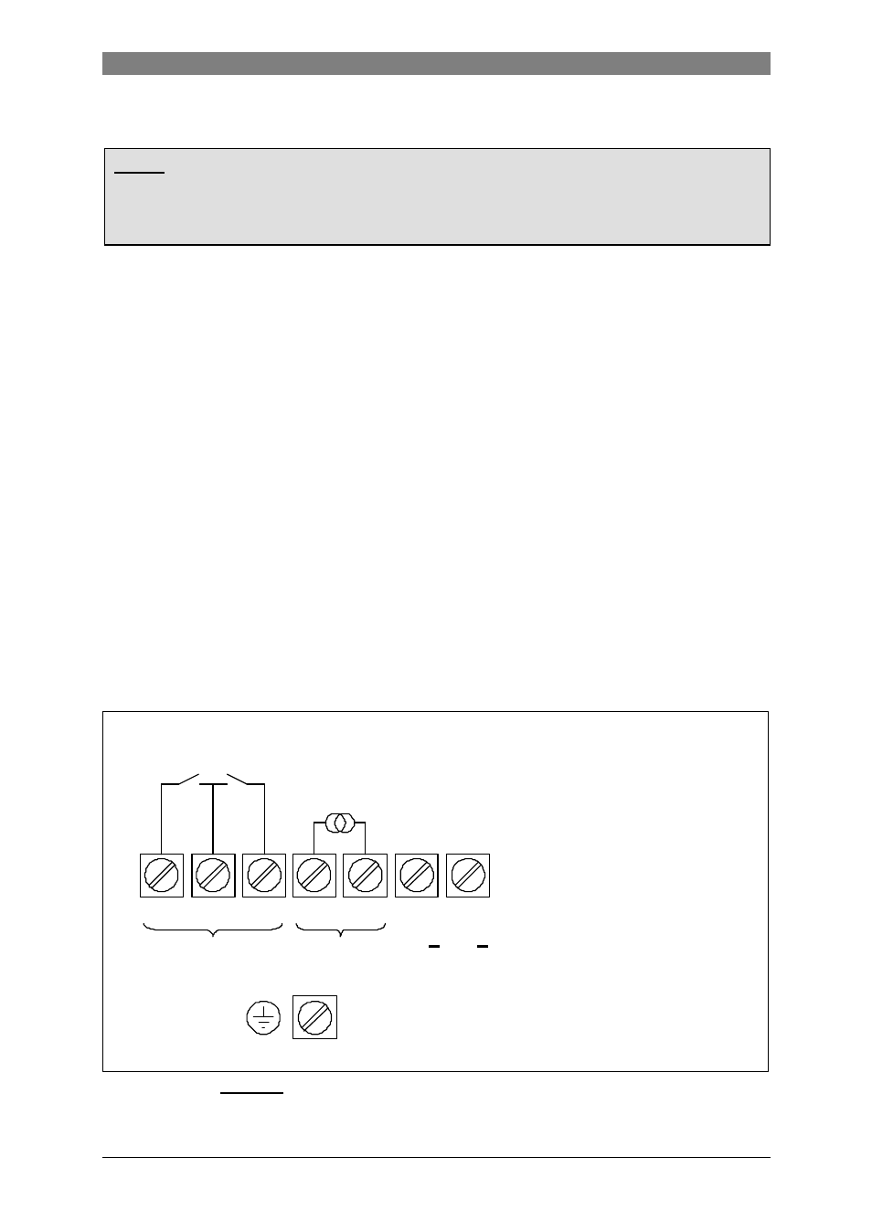
The arrangement of the terminals in the terminal compartment is shown in Figure 1 below.
For mains voltages above 50 Vac the PE conductor must be connected to the PE-terminal in
the terminal compartment.
To connect external devices to the current and binary output terminals, the wiring
requirements for the specific type of protection of the terminal compartment (standard:
increased safety "e", special version: flameproof enclosure "d") must be respected, see the
EN 60079-14 or corresponding national standard.
2.1 Potential equalization
The UFM 500 K-EEx ultrasonic compact flowmeter must always be connected to the
equipotential bonding system of the hazardous area. For this purpose the internal PE-
terminal (over the PE-conductor of the mains) or the external PE-terminal may be used.
The external PE-terminal is placed halfway converter housing and primary head.
A separate bonding conductor must be at least 4 mm
2
, or 2,5 mm
2
if mechanical protected,
see clause 413 of HD 384.4.41or IEC 364-4-41 for additional information.
When the UFM 500 K-EEx is incorporated in the equipotential bonding system, make sure
that the core of the bonding wire is properly mounted under the U-clamp of the PE-terminal
and that the screw is tightly fixed.
Figure 1: Arrangement of terminals in terminal compartment.
B1
B
⊥
B2
I+
I
L
N
(100…240V AC / 48…63 Hz)
L~ L~ (24V AC/DC)
BINARY
CURRENT
OUTPUTS
OUTPUT
PE (Protective Earth) terminal
FE (Functional Earth) terminal
Pulse
Status
output
output