KROHNE UFM 500 ATEX EN User Manual
Page 10
9
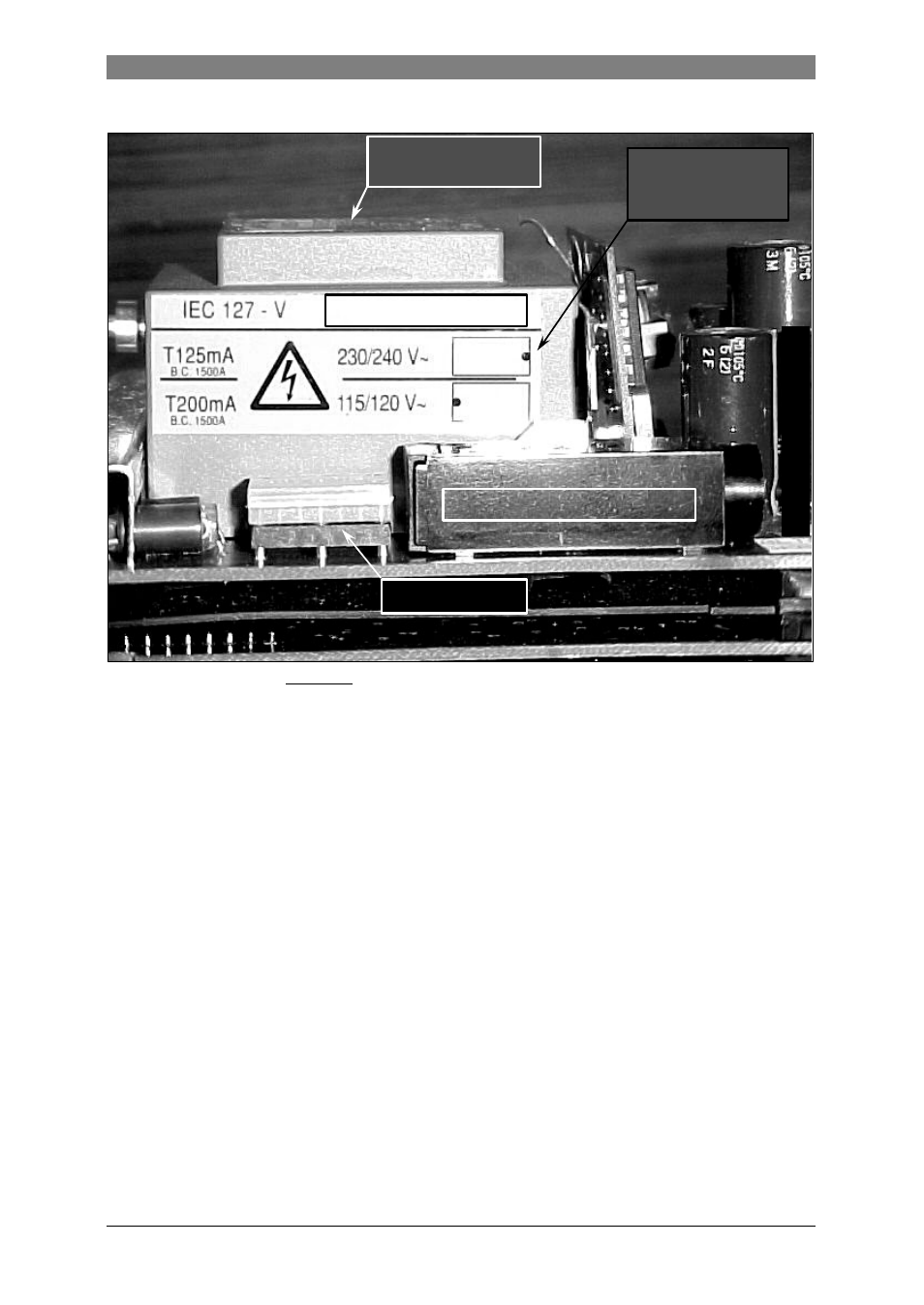
Figure 6: Power supply version 115/230 V AC.
b) 24 V AC/DC version
Before commencing work,
note the instructions in Section 4.1 ("Before opening")
.
Then continue as follows:
1. Loosen the interlocking device and remove the cover of the electronics compartment.
2. Unscrew the two screws A (see figure 5 in section 4.1) of the display unit and disconnect
the display unit via the flat cable connector (see the right picture of Figure 5 on the
previous page).
3. Unscrew the brass earth strip (screw C) with the and the mounting screws B of the
electronics unit. Pull the unit out until the SMB connectors of the coaxial cables can be
disconnected from the electronics. Then take out the complete electronics unit. Be careful
with the coaxial cables, so that they do not damage while removing the electronics unit
from the flow converter housing.
4. The mains fuses F1 and F2 (see Figure 7 on the next page) can be replaced now. The
24 V AC/DC power supply uses two sub-miniature fuses rated T1.25A in accordance with
IEC 127-3 publication.
5. Reassemble in reverse order (points 3 through 1).
Note the instructions of section 4.1 ("After opening") during reassembling.
Mains transformer
115/230 V
AC
version
Mains fuse F1 (in fuse -holder)
Sticker with fuse rating
Voltage selector
SIDE OF DISPLAY UNIT
Indication of
voltage selector
(black dot = notch)