Electrical connections – KROHNE DK 37 NEPSI Ex i User Manual
Page 10
4
ELECTRICAL CONNECTIONS
10
DK37/M8 - H250/M8
www.krohne.com
09/2013 - 4002616801 AD DK37 NEPSI Ex ia R01 en
Electrical connections
4.1 General notes
The limit switch or electronic signal output with protection level "ia" or "ib" is electrically
connected in the terminal compartment of the display housing. Permissible maximum values
(electrical data) must be observed. Observe the specified polarities.
Connecting cable
The connecting cables must be selected according to prevailing installation standards. The outer
diameter of the connecting cable must be within the sealing range of the cable entry. The
connecting cables must be fixed and laid so they are sufficiently protected against damage. All
cores that are not used must be securely connected to the earth potential of the hazardous area
or carefully insulated against each other and against earth (test voltage ≥ 500 V
eff
).
Connection diagrams
Cable entries / Blanking plugs
The variable area flowmeter is equipped as standard with a blanking plug and a cable entry.
These elements guarantee protection from foreign bodies and water (protection type) IP65 in the
temperature range of Tamb = -40...+100°C / -40...+212°F. The cable entries provided also ensure
protection from foreign bodies and water. The nominal diameter range of the cable entries is
3...7 mm. Suitable blanking plugs and seals are to be used for unused cable entries. Ensure that
the seals are tight.
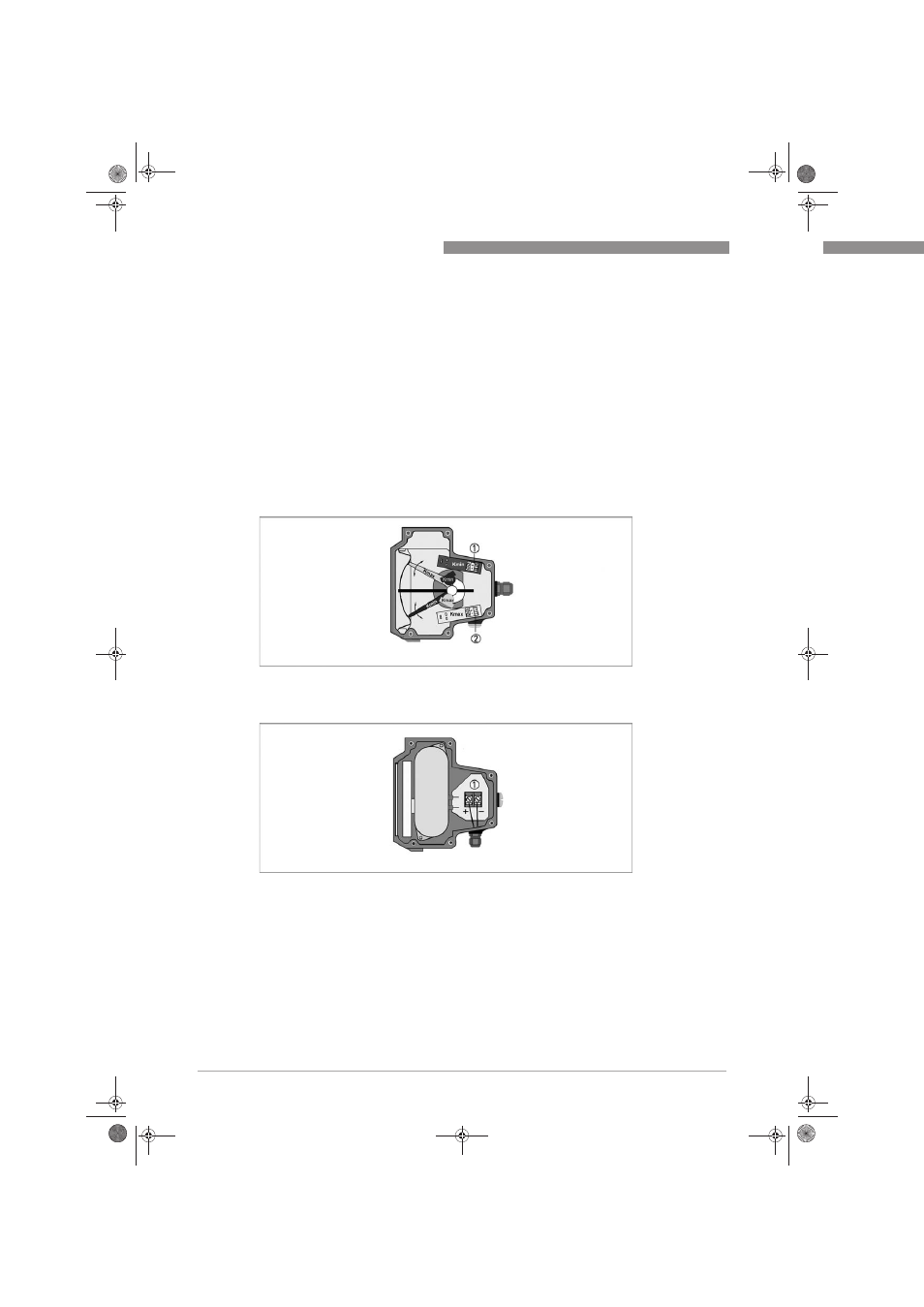
Indicator M8M - M8MG
1 Terminal Kmin
2 Terminal Kmax
Indicator M8E - M8EG
1 Terminal signal output 4...20 mA
AD_DK37_NEPSI_Ex_ia_R01_en_4002616801_PRT.book Page 10 Friday, September 13, 2013 8:50 AM