Device description, 8 electrical data – KROHNE H250 M40 NEPSI Ex nA User Manual
Page 13
DEVICE DESCRIPTION
2
13
H250 M40
www.krohne.com
03/2013 - 4002616601 AD H250 M40 NEPSI Ex nA R01 en
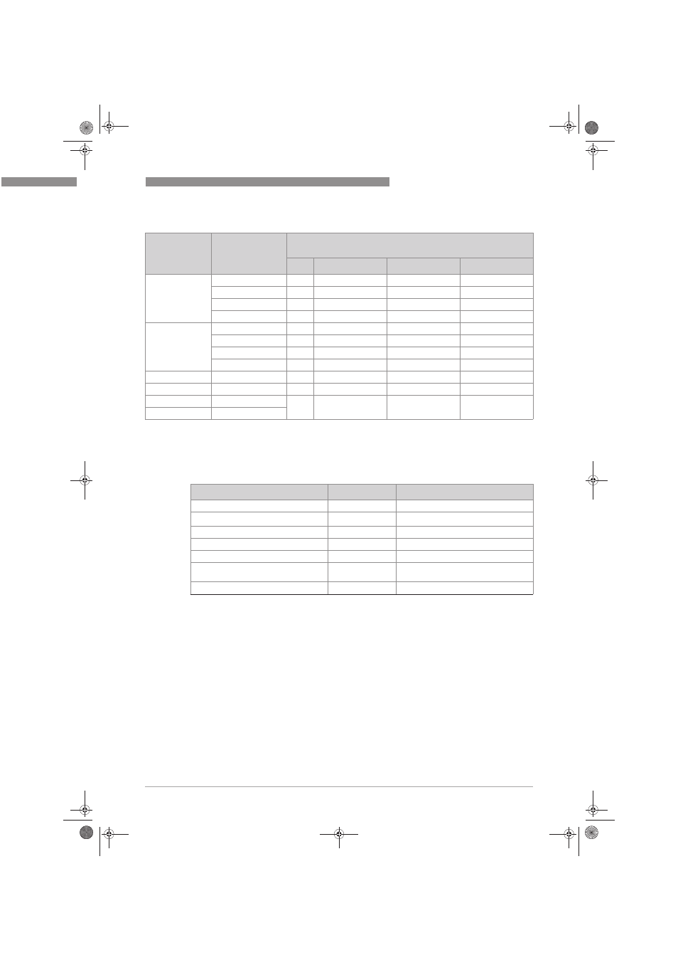
Maximum permitted temperatures at reference point of indicator in °F
2.8 Electrical data
Design of
indicator
Component
Permitted temperature range at reference point T [°F] according to
temperature class
TK T6
T5
T4 ... T1
M40./../K.
SC3,5-NO-Y
-4 ... +149
-4 ... +176
-4 ... +194
SJ3,5-SN
-4 ... +151
-4 ... +178
-4 ... +194
SJ3,5-S1N
-4 ... +151
-4 ... +178
-4 ... +194
I7S23,5-N
-40 ... +158
-40 ... +185
-40 ... +194
M40./../ESK4/K.
SC3,5-NO-Y
-4 ... +131
-4 ... +158
-4 ... +176
SJ3,5-SN
-4 ... +131
-4 ... +158
-4 ... +176
SJ3,5-S1N
-4 ... +131
-4 ... +158
-4 ... +176
I7S23,5-N
-40 ... +131
-40 ... +158
-40 ... +176
M40./../ESK4
ESK4
-40 ... +131
-40 ... +158
-40 ... +176
M40./../ESK4-T
ESK4 and I/O modul
-40 ... +126
-40 ... +153
-40 ... +171
M40./../ESK4-FF
ESK4 and ESK4-FF
-40 ... +97
-40 ... +124
-40 ... +169
M40./../ESK4-PA
ESK4 and ESK4-PA
Electrical equipment
Rated voltage
Nominal current
Limit switch K1 / K2
8 VDC
≤1 / ≥3 mA
Signal output ESK4
14 - 32 VDC
4...20mA with HART
®
communication
Switching output ESK4-T OC output
8 - 32 VDC
1...100 mA
Switching output ESK4-T NAMUR output 8 VDC
≤1 / ≥3 mA
Signal input ESK4-T input
8 - 32 VDC
≤2 mA
ESK4-FF Foundation Fieldbus
transmitter
1
9 - 32 VDC
16 mA
ESK4-PA Profibus transmitter
2
9 - 32 VDC
16 mA
1 Further information and instructions for operation of the ESK4-FF transmitter are provided in separate supplementary
instructions.
2 Further information and instructions for operation of the ESK4-PA Profibus transmitter are provided in separate sup-
plementary instructions.
AD_H250_M40_NEPSI_Ex_nA_R01_en_4002616601_PRT.book Page 13 Friday, March 8, 2013 8:50 AM