KROHNE CORIMASS E P MFM 2081 EEx EN User Manual
Page 9
Additional Instruction for Ex version MFM 2081 / 3081
9
2.3
Electrical connection on converter with intrinsically safe
outputs
Please ensure that the instrument power supply information given on the data plate
corresponds to the locally available power supply to be used.
•
Note information given on the instrument data plate (voltage,frequency)!
•
Electrical connection in conformity with IEC 364 or equivalent standard.
•
The PE ground conductor must be connected to the seperate U-clamp terminal in the
terminal box of the signal converter.
•
Do not cross or loop the cables in the back of the converter. Please use seperate cable
entries (PG or NPT) for power and signal cables.
Ensure that the screw thread of the round cover on the terminal box is well greased at
all times.
•
NOTE: The grease used must be non corrosive to aluminium; typically it must be resin-
and acid free.
•
Protect the sealing ring from damage.
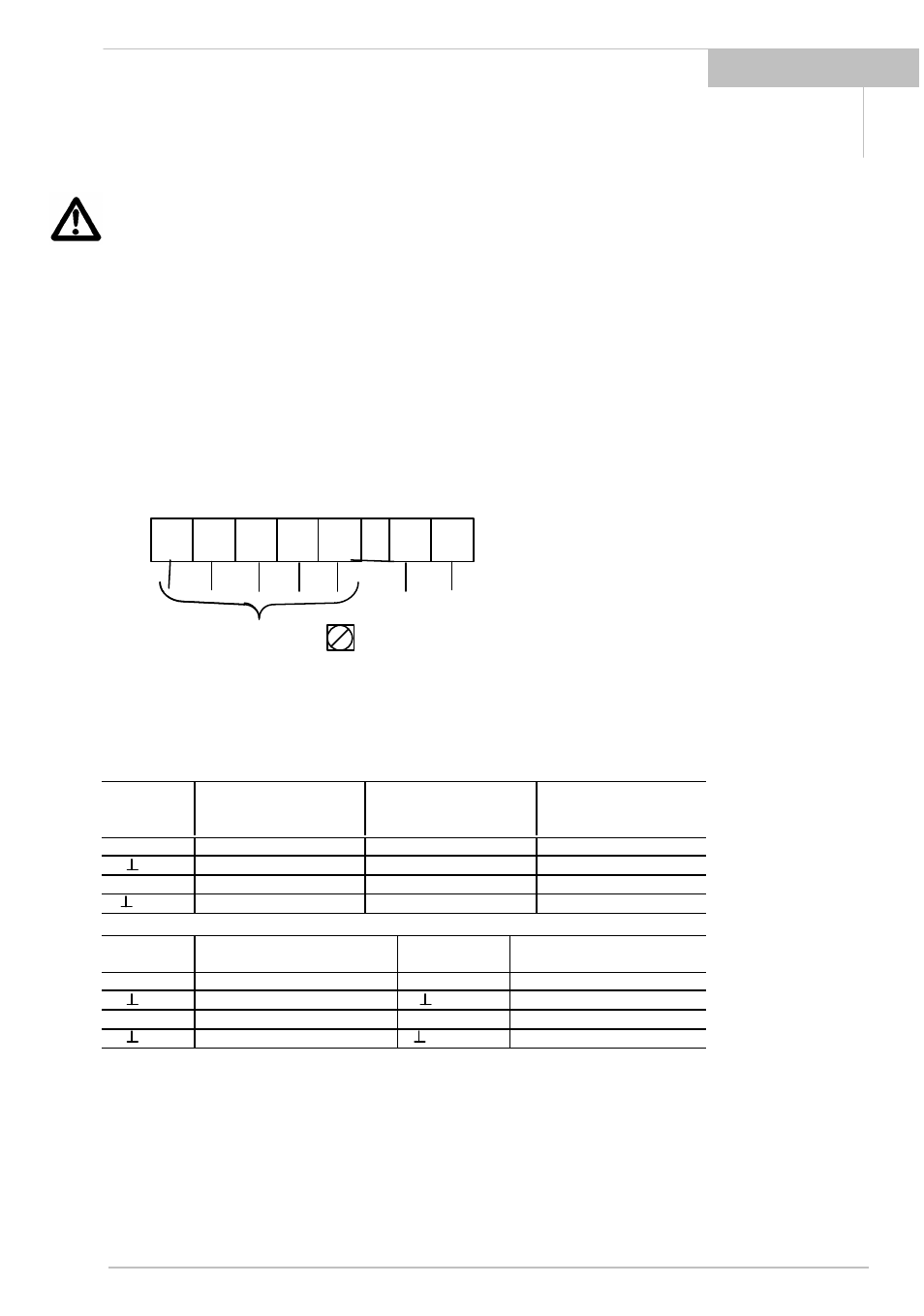
11 12
- + DC
Coding of the
Outputs acc. PE
to following table
Fig. 5: Power and signal connections for MFC 081 K/F with intrinsically safe outputs
Coding of Outputs
Term. No.
Variant G
(1 Current, 1 Pulse
intrins.safe)
Variant H
(1 Current, 1 Status output
intrins.safe)
Variant K
(1 Current, 1 Control input,
intrins.safe)
I 1
Current output (+)
Current output (+)
Current output (+)
I 1
Current output (-)
Current output (-)
Current output (-)
B
Current output (+)
Status output. (+)
Control input(+)
B
Pulse output (-)
Status output. (-)
Control input(-)
Term. No.
Variant L
(2 Current, intrins safe)
Term. No.
Variant M
1Current, 1 Bus intrins.safe)
I 1
Current output 1 (+)
I 1
Current output 1 (+)
I 1
Current output 1 (-)
I 1
Current output 1 (-)
I 2
Current output 2 (+)
D
Bus
I 2
Current output 2 (-)
D
Bus