2 bus cable, 3 shielding and grounding, 4 profibus-pa connection – KROHNE BM 70A-P PROFIBUS PA DE User Manual
Page 7: Us cable, Hielding and grounding, 4 profibus-pa, Connection, Electrical connection
Supplementary Documentation BM 70 A, BM 70 P with PROFIBUS-PA
2. Electrical connection
(see Section 7.8 in the Installation and Operating Instructions)
2.1 Interconnection of devices in the hazardous location
We recommend that a PROFIBUS-PA network in the hazardous location be projected in accordance with PTB’s
FISCO model (see KROHNE brochure ”PROFIBUS-PA networks”). The FISCO-Model may be used, if:
all electrical components which should be connected to the bus must be approved according the FISCO model (even
the termination),
the maximum cable length does not exceed 1000 m,
the values of the cable are within the following ranges R´=15...150
W/km; L´=0,4...1mH/km; C´=80...200nF/km,
the approved input values of the field devices (Uo, Io, Po) are matchable with the output values of the power supply
(e.g. segmment coupler) which menas U
I
£ Uo,
I
I
£
I
o und P
I
£ Po.
2.2 Bus cable
Further limitations to the cable than the FISCO limitations are not existent. Nevertheless a twisted pair and shielded
cable is strongly recommended. The good quality cable could have the following data: 44
W/km, <90nF/km, <3dB
attenuation at 39kHz and 100 Ohm impedance at 31,25kHz.
2.3 Shielding and grounding
For optimum electromagnetic compatibility of systems it is extremely important that the system components, and
particularly the bus cables connecting the components, be shielded and that such shields - if possible - form an
unbroken cover, electrically speaking.
Hence it follows that, for use in non-hazardous duty systems , the cable shield should be grounded as often as
possible.
In “Ex“ systems an adequate equipotential bonding in the hazardous and non-hazardous location along the entire
fieldbus installation is strongly recommended. Multiple grounding of the shield is also of advantage.
Note: The use of twisted and shielded cables is strongly recommended, otherwise EMC protection of the BM 70 A/P
cannot be assured.
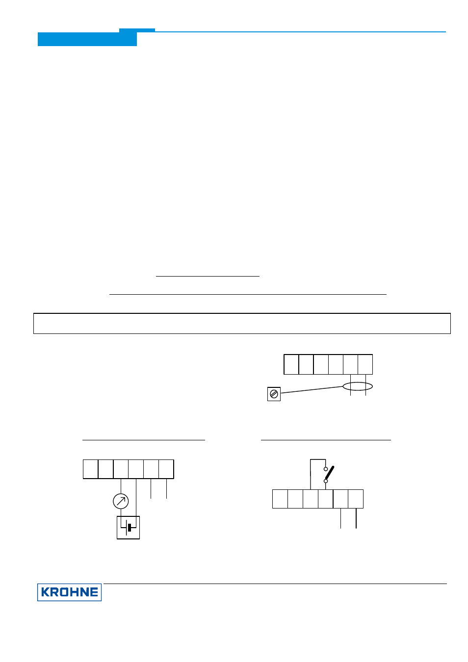
2.4 PROFIBUS-PA connection
Connect the bus cable as shown in the figure.
· Connect cable cores to terminals 31 and 32.
· Polarity reversal will not have any effect.
· The cable shield should be connected with minimum
length to the functional ground FE.
· The equipotential bonding conductor must be connected
to the device, if necessary via the outer U-clamp ground
terminal.
32 31
bus-
connection
FE
PROFIBUS-PA with current output:
PROFIBUS-PA with switching output:
42
-
Ex-i-feeder-
+
+
unit
+
U max.= 30V
current-
output
4-20mA
U min.
= 8V
41
-
32 31
bus-
connection
32 31
switching output
max. 110mA/30V
42 41
bus-
connection
KROHNE Messtechnik GmbH & Co. KG · Ludwig-Krohne-Str. 5
D-47058 Duisburg
7/7
Tel.: 0203-301 309 Fax: 0203-301389 · e-mail: [email protected]