Specification of the safety function – KROHNE H250 M9 Safet V2 EN User Manual
Page 6
4
SPECIFICATION OF THE SAFETY FUNCTION
6
H250 M9
www.krohne.com
06/2013 - 4000656702 MA H250-M9 SIL R03
Specification of the safety function
4.1 Description of the failure categories
In order to judge the failure behavior of the variable-area flowmeter H250/M9 with limit switch
output, the following definitions for the failure of the product were considered.
In IEC 61508 edition 1 the “No Effect” failures were defined as safe undetected failures, even
though they would not cause the safety function to go to a safe state.
With edition 2 (IEC 61508:2010) the no effect failures are no longer considered as safe
undetected failures and must not contribute to the SFF calculation. Therefore the SFF values
have changed.
The PFD values remain as before.
The demand response time of H250 M9 is < 2s.
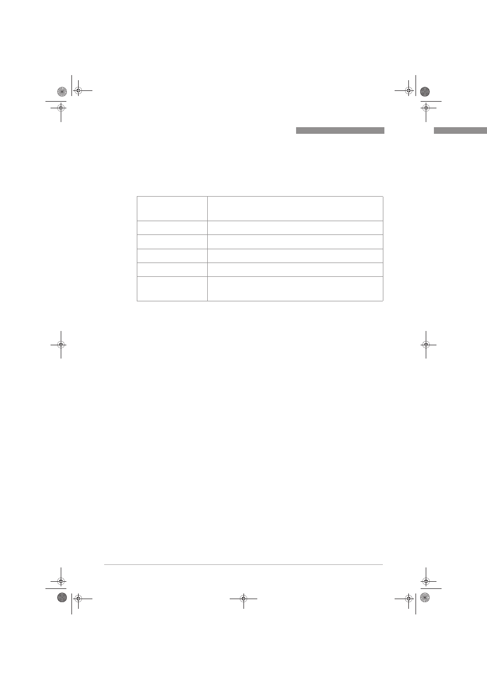
Fail-Safe State
The fail-safe state is defined as the output being de-energized or one of
the 2 limit switches is triggered. Fail Safe Failure that causes the module /
(sub) system to go to the defined fail-safe state without a demand from the
process.
Fail Dangerous
Failure that does not respond to a demand from the process (i.e. being
unable to go to the defined fail-safe state).
Fail Dangerous Undetected
Failure that is dangerous and that is not being diagnosed by internal
diagnostics.
Fail Dangerous Detected
Failure that is dangerous but is detected by internal diagnostics. (These
failures may be converted to the selected fail-safe state.)
Not Effect
Failure of a component that is part of the safety function but that has no
effect on the safety function.
Not part
Failures of a component which is not part of the safety function but part of
the circuit diagram and is listed for completeness. When calculating the
SFF this failure mode is not taken into account. It is also not part of the
total failure rate.
MA_H250_M9_SIL2_R03_en_656702_PRT.book Page 6 Wednesday, June 26, 2013 9:08 AM