Caution – HT instruments HT9015 User Manual
Page 12
HT9014 - HT9015
EN - 11
4.3.4. Continuity test and Diode test
CAUTION
Before taking any in circuit resistance measurement, remove power from
the circuit to be tested and discharge all the capacitors.
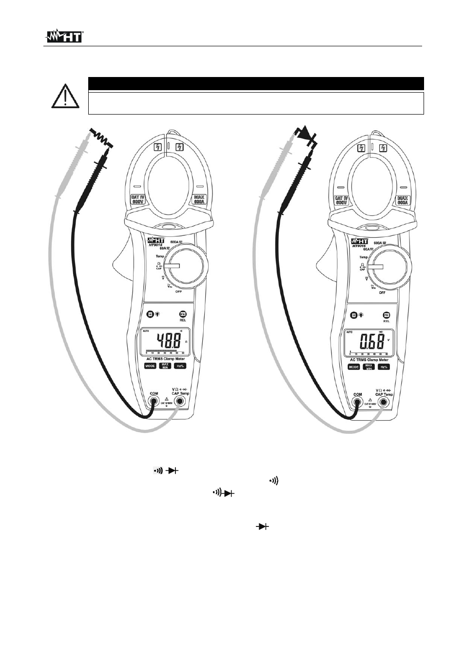
Fig. 6: Taking Continuity test and Diode test
1. Rotate the switch on
Ω
CAP
position
2. Pushing MODE key and select continuity test. The
symbol is shown at display
3. Insert the red test lead plug into V
Ω
CAPHz%Temp
jack and the black test lead
plug into COM jack and perform continuity test on the object under test (see Fig. 6 –
left side). Buzzer emits sound if the measured resistance value is less about 60
Ω
4. Pushing MODE key and select diode test. The “
”
symbol is shown at display
5. Connect the red test leads to the anode of diode on test and the black test lead on the
cathode ones (see Fig. 6 – right side). Reverse position of test leads to reading reverse
polarization voltage
6. Displayed values within 0.4V and 0.7V (direct junction) and “OL” (reverse junction) are
correspondent to a correct result. A “0mV” value means a shorted device while a “OL”
indication in both side means a broken device. Bargraph is disabled in diode test