Figure #5a – Detcon FP-624C User Manual
Page 12
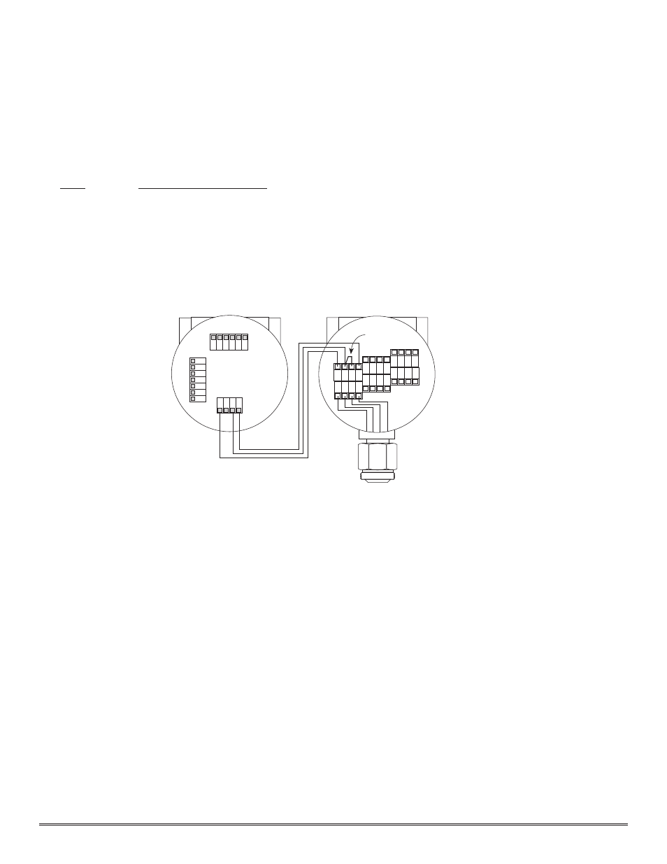
3.5.6 Remote Mounting Applications
Some sensor mounting applications require that the gas sensor head be remotely mounted away from the sensor
transmitter. This is usually true in instances where the gas sensor head must be mounted in a location that is diff i-
cult to access. Such a location creates problems for maintenance and calibration activities. Detcon provides the FP-
624C sensor in a remote-mount conf iguration in which the sensor (Model FP-624C-RS) and the transmitter (Model
FP-624C-RT) are provided in their own condulet housing and are interfaced together with a three conductor cable.
There is a limit 0.5 ohm maximum resistance drop per wire over the seperation distance.
AWG
Maximum Seperation (feet)
20
50
18
75
16
125
14
175
Reference f igure 5A for wiring diagram. Also note the jumper that is required on the remote sensor connector
board. Failure to install this jumper will cause a sensor fault condition.
Remote Mounting Configuration - Bridge Voltage Adjustment
When a sensor is remotely mounted away from the transmitter, consideration must be given to the lengths of cable
used and how it affects the sensor bridge voltage. Differing lengths of cables will have varying amounts of resistance
which will will shift the sensor bridge voltage. Because of this, the bridge voltage will need to be adjusted after ini-
tial power up. This adjustment is only required after initial installation and will not be necessary thereafter, even in
the event of replacement of the plug-in sensor. See section 3.6.1 for instructions.
3.6 S
TART
U
P
Upon completion of all mechanical mounting and termination of all f ield wiring, apply system power and observe
the following normal conditions:
a)
FP-624C “Fault” LED is off.
b)
A temporary upscale reading may occur as the sensor heats up. This upscale reading will clear to “0”
% within 1-2 minutes of turn-on, assuming there is no gas in the area of the sensor.
Note 1:
All alarms will be disabled for 1 minute after power up. In the event of power failure, the alarm disable peri-
od will begin again once power has been restored.
Note 2: If the display contrast needs adjustment, refer to section 3.11.
Note 3: If the sensor has been installed using the remote mounting conf iguration as described in section 3.5.5, the
sensor bridge voltage must be adjusted after initial power up. If this is the case, f irst adjust the bridge voltage as
described in section 3.6.2, then proceed with the initial operation tests below (section 3.6.1).
Model FP-624C Combustible Gas Sensor PG.12
1 2 3 4
W
H
T
B
L
K
Y
E
L
B
LU
Install
Jumper
Remote Transmitter
FP-624-RT
Remote Sensor
FP-624-RS
Measure Bridge Voltage
From White (1) to Blue (4)
Target voltage is 2.7v
W
H
T
B
L
K
Y
E
L
B
LU
Figure #5A