Enjoy your mount, Step 5, Step 6 – Video Mount Products LCD-DM2 User Manual
Page 4: Step 7
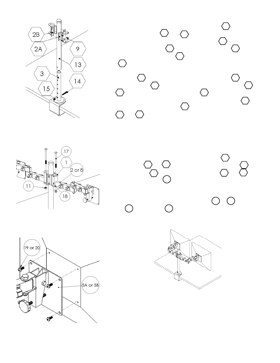
Step 5
Now is time to adjust height of the upper tube
LCD-DM2 and
connectors A and B and
LCD-DM2 to the desired height of
your TV. To adjust the height of the upper tube
LCD-DM2 simply
remove the M8 screw
LCD-DM2 and nylon nut LCD-DM2.
Next slide the upper tube
LCD-DM2 along the bottom tube
LCD-DM2 matching up the height adjustment holes on the
two of them until you get your desired height. Then secure the up-
per tube
LCD-DM2 again using the M8 screw LCD-DM2
and nylon nut
LCD-DM2. To adjust the connectors and
LCD-DM2 loosen the M6 screws LCD-DM2 and slide the
connectors to the desired height along the upper tube
LCD-
DM2. Retighten the screws LCD-DM2 once the connectors
and
LCD-DM2 are in the proper position.
Step 6
For this step it is assumed that you have assembled the LCD-1 to
the confi guration desired, but have not attached the monitors to
the mounting plates. If this is not the case, please take the time to
assemble the LCD-1. Insert the plastic fl anges
LCD-1 into the
desired arm or
LCD-1. Now use the 3/8” bolt LCD-1
and nylon nut
LCD-1 to connect the arm or LCD-1
to the “U” connector
LCD-DM2.
Step 7
Attach the monitors to the mounting plate or
LCD-1 using
M4
LCD-1 or M5 LCD-1 screws. Please verify that all nuts
and screws are tight.
Step 5: Adjusting height
Step 6: Attaching LCD-1s
Step 7 : Attaching monitors
3
13
1
19
20
WARNING: The installer of these products must verify that the mount-
ing surface, ceiling or wall, will safely support the combined weight
of all attached equipment and hardware. Video Mount roducts will
not be held liable for the improper use or installation of its products.
Enjoy Your Mount!
2A
2B
2B
2A
15
14
13
13
15
14
13
9
2A
9
13
2B
5A
5B
11
17
18
8
2
8
2