Assembly of technical workstation, Figure 1 figure 2 figure 3 figure 4 – Tennsco Technical Workstation User Manual
Page 2
9
8
3
8
4
3
7
4
11
12
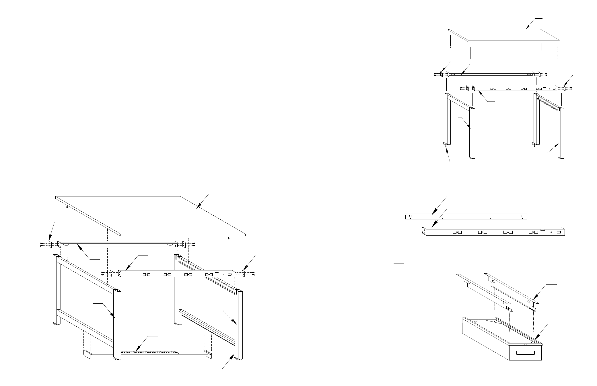
Assembly of Technical Workstation
Tools required: Rubber Mallet, slotted screwdriver, and a ratchet
with
1
2
" and
7
16
" sockets (a socket extension is desirable).
BASIC WORKSTATION (Refer to Figure 1):
1. Carefully remove all parts and hardware from
packaging, identifying each item with parts list shown
on the back of this instruction sheet. Hardware for the
basic unit is packaged with the leg assembly.
2. Attach a reinforcing plate (Ref. No. 3) to each end of
support channel (Ref. No. 4) with
5
16
"-18 x 1
1
4
"
carriage bolts, lock washers and nuts. At this time,
hand tighten only so that
1
4
" of space remains
between reinforcing plate and end of support channel.
NOTE: If assembling unit with optional instrument shelf,
use the 1
1
2
" x 1
1
2
" reinforcement plate at this time. The
1
1
4
" reinforcement plate is for the instrument shelf (see
instructions on next page).
3. Repeat step 2 for remaining support channel.
4. Attach footrest (Ref. No. 5) by positioning hanger
brackets of footrest into adjusting channel (lower
member) of both leg assemblies (Ref. No. 2), making
sure that the black slip resistant surface of the footrest
is facing the working side of the workstation. Lock
brackets into slots at desired position.
NOTE: Footrest assembly is not designed for use on 30"
high workstations equipped with optional TWD-20 or
TWD-30 drawer units.
5. Locate previously assembled support channels to leg
assemblies (Ref. No. 2) by sliding slotted side of leg
assemblies in position between reinforcing plate and
end of support channel.
6. If drawer units are to be installed, refer to DRAWER
UNITS section on next page.
7. Position top (Ref. No. 1) onto previously assembled
frame, taking care to line up threaded inserts with slots
in leg assembly upper member.
8. Secure top to frame with
1
4
-20 x
5
8
“ slotted truss- head
bolt.
9. Tighten all bolts, taking care that all parts are properly
seated.
10. Unit may be leveled to suit by adjusting leveling screws
at bottom of each leg (Ref. No. 6).
INSTRUMENT SHELF (Refer to Figure No. 2)
1. Place top (Ref. No. 7) on either padded sawhorses or
on protected floor so that the threaded inserts on the
underside of the top face upward.
2. Attach a reinforcing plate (Ref. No. 3) to each end of
support channel (Ref. No. 4) with
5
16
-18 x 1
1
4
"
carriage bolts, lock washers and nuts. (Tighten only
slightly at this time, leaving
1
4
" of space remaining
between reinforcing plate and end of support channel).
3. Repeat step 2 for remaining support channel.
4. Place support channels into approximate position on
the top and slide slotted side of upright assemblies
(Ref. No. 8) into place between support channel ends
and reinforcing plate (do not tighten at this time).
5. Attach upright assemblies to top with
1
4
x 20 x
5
8
"
slotted, truss head bolts.
6. Insert adjusting screws (Ref. No. 9) into bottom of
upright assemblies for clamping onto workstation top.
7. Tighten all bolts, taking care that all parts are properly
seated.
ELECTRICAL POWER RAILS (Refer to Figure 3)
1. Separate wire cover (Ref. No. 10) from power rail (Ref.
No. 4) by removing screws, leaving power cord
attached.
2. Follow assembly instructions for workstations or
instrument shelves, treating power rails in same
manner as standard support rails.
3. Replace wire cover by securing
with self tapping screws,
previously removed, making
certain that wires are not
trapped under cover.
4. Finish assembly by completing
the assembly instructions for
workstations or instrument shelves.
DRAWER UNITS (Refer to Figure 4)
Note: Completed drawer assembly must be located onto
workstation prior to attaching top to frame.
1. Position drawer hanger brackets (Ref. No. 11) on top
of mounting channels of drawer unit (Ref. No. 12) as
shown in Figure 4. Secure with
1
4
x 20 x
5
8
bolt and
J-clip.
2. Lift assembly over workstation frame and lower into
position, making certain that the brackets seat over
support channel rails on workstation securely
(Individual drawers may be removed to lighten unit).
3. Position drawer assembly at desired location before
attaching top.
4. Complete workstation assembly by referring back to
BASIC WORKSTATION step 6.
1
3
2
6
5
3
4
4
2
10
4
FIGURE 1
FIGURE 2
FIGURE 3
FIGURE 4