Handle/locking system installation instructions – Tennsco 1480 User Manual
Page 3
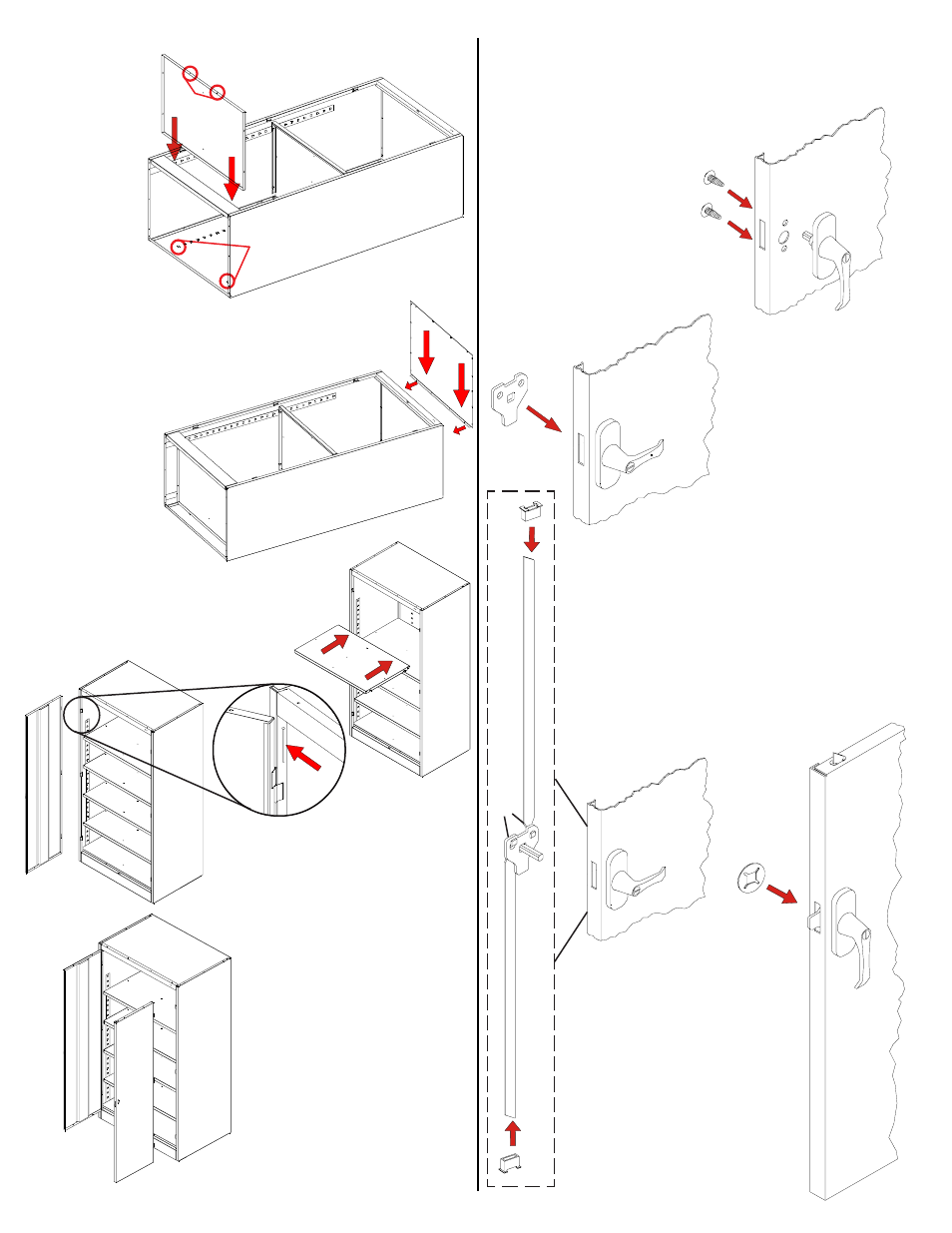
2.
Turn the handle to
the open position,
and place the
locking cam (Ref.
No. 13) over the
square shank of
the door handle.
The latch must be
facing downward
as shown.
8.
Place the bottom (Ref. No. 7) in the bottom
lances of
the shelf adjustment strips. The
flange with
two holes
should
face the
front, and
it should
hang over
the sill.
Bolt to the
sill with two
two bolts and nuts.
9.
Attach the top (Ref. No. 8) by sliding it
under the header and sides, with the
flange hanging over the back.
Secure with 14 bolts
and nuts (three
along each
side, four
in the back,
and four
along the
front).
11.
Attach the left door
(Ref. No. 9) to the unit by
placing the door on the hinges,
aligning the holes, and using
a hammer to tap the hinge
pins (Ref. No. 16) into place
with the side of a screwdriver.
10.
Set the unit upright and insert
the remaining shelves at
your desired levels.
Insert shelf into
bottom lances.
Two
hole
s m
ust
be in
fro
nt.
12.
Attach the right door
(Ref. No. 10) to the unit
in the same way you
attached the left door.
1.
Place the locking
handle (Ref. No. 12)
on the right hand
door and fasten with
two slotted bolts with
lockwashers.
Handle/Locking System Installation Instructions
4.
Place the locking cam
retainer (Ref. No. 14)
over the square
shank of the door
handle. Tap on the
edges of the cam
retainer with a
hammer until retainer
sits firmly against the
locking cam.
3.
With the handle still in the open
position, hook the locking bars (Ref.
No. 11) to the locking cam (see "A" at
left). Then, hold the lock bars in
position while sliding the nylon lock
bar guide inserts (Ref. No. 15) over
the lock bar ends and through
the door slots (see "B" at left).
A
B
B