Tele Vue NP101 User Manual
Page 2
However, Tele Vue developed the 1¼” 60° Everbrite Diagonal (part# DPC-6012) specifically for
terrestrial observers who appreciate the highest levels of image performance. The 60° angle is far more
comfortable for terrestrial observing than the standard 90°, and the 99% reflective Everbrite dielectric
coating gives the truest color rendition of any mirror or prism, and is sharpest at the highest powers.
For correct left-right viewing, use the Tele Vue 45° erector (part# AMI-0011). Barlows, Powermates
and Bino Vue are not recommended with the 45° erector. For 1¼” diagonals and prisms, the 32mm
Plössl, or 24mm Panoptic offers the maximum field. 2.9° at 17x and 22.5x respectively.
Getting Acquainted with the Tele Vue-NP101
1.1 Optical tube assembly
The optical tube consists of an air-spaced doublet within the front cell. The front cell is attached to the
tube via three alignment locking screws which you’ll see when sliding the dew shield forward. (Warning:
Loosening these screws will ruin the collimation.) The rear doublet, making up the rest of the objective is
housed in the cell that threads between the back of the tube and the focuser. Do not stick any long objects
into the focuser or you will hit the rear most lens surface.
1.2 Focuser
The 2” focuser is a custom fitted rack and pinion type which is capable of supporting the heaviest accesso-
ries without slipping. The left side focuser knob and inner knob on the right side are a 1:1 ratio. The outer
(smaller) knob on the right side is a 10:1 ratio, which will help in fine focusing for planets and photography.
The two tension screws on the top of the focuser body can be adjusted to add resistance when
using heavy eyepieces or cameras. These tension screws tighten against a brass clamp ring, which then
cinches down on the Teflon sleeve in which the draw tube slides. For photography it is not necessary to
tighten beyond the need to keep a camera stationary. Even when sufficiently tight, the focuser knobs can
still drive the draw tube.
The focuser body is pre-drilled to accept the Digital Indicator Kits (RMK-2002/RMF-2003) for focus
accuracy down to 1-micron. The dual speed pinion assembly is pre-drilled to mount the 10:1 Focusmate
Driver (FDF-2004). (See section 1.5 Photography)
The two lock screws in the end of the draw tube also tighten against a brass clamp ring for extra
holding power on the diagonal or other accessories.
1.3 Ring Mount
The Ring Mount permits easy telescope balancing. Simply loosen the “bat handle,” reposition the O.T.A.
and re-lock the bat handle. The Ring Mount base is blind tapped with three ¼”-20 threaded holes so
screws cannot hit the tube. The two accessory channels are tapped with #10-32 threaded holes.
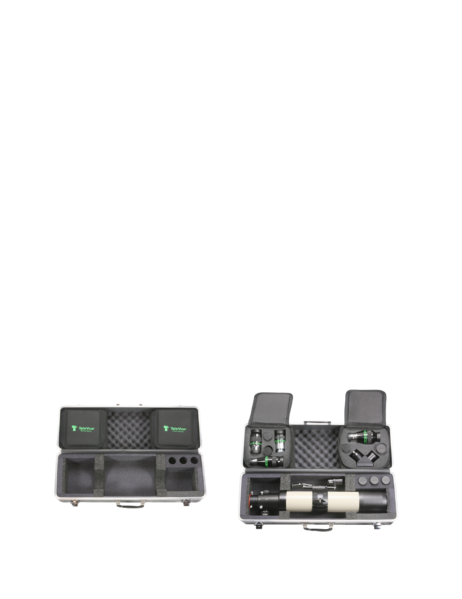
1.4 Case
When opening the case, we recommend always lift-
ing the lid while holding the handle. The lid opens a
full 180° and holding the handle will give you a better grasp to insure that the lid doesn’t slip out of your
hand. The interior of the case was designed to store your scope with the optional Starbeam, Focusmate
Motor Driver and Digital Indicator Kit installed. To fit the Starbeam, you may have to slide your ring mount
so that the Starbeam fits in the lid of the case between the accessory bags.
Optional Accessories Shown