Wiring tables – Aube Technologies Programmable H/C Controller TH146-P-U User Manual
Page 4
TH146-P-U
4/12
Wiring Tables
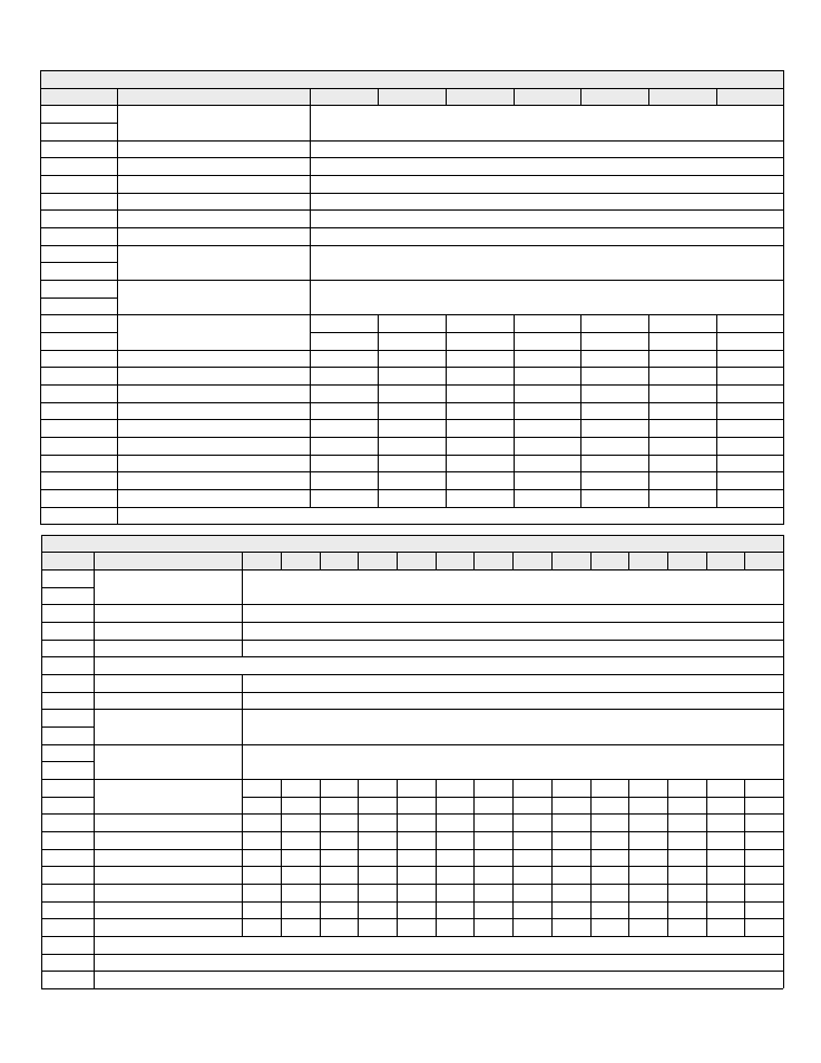
Heat Pump
Terminal
Device
1H1C
2H1C
3H1C
2H2C
3H2C
4H2C
3H3C
TH
Console
Connect the console between the TH terminals (no polarity)
TH
PS
Plenum sensor
Connect the plenum sensor between the PS and CS terminals (no polarity)
CS
Common S
Common terminal for the plenum sensor and the outdoor sensor
OS
Outdoor sensor
Connect the outdoor sensor between the CS and OS terminals (no polarity)
DE
Dual Energy
Connect the dual-register meter between the DE and CC terminals (no polarity)
CC
Common C
Common terminal for the dual-energy meter and the unoccupied mode input
UN
Unoccupied mode input
Connect a dry contact between the UN and CC terminals (no polarity)
H
Humidifier (24 Vac / 1 A)
Connect the humidifier between the H terminals (dry contact)
H
D
Dehumidifier (24 Vac / 1 A)
Connect the dehumidifier between the D terminals (dry contact)
D
R
Power (24 Vac)
C
Y1
Compressor 1 (24 Vac / 1 A)
Y2
Compressor 2 (24 Vac / 1 A)
Y3
Compressor 3 (24 Vac / 1 A)
W1
Auxiliary heat 1 (24 Vac / 1 A)
W2
Auxiliary heat 2 (24 Vac / 1 A)
W3/O/B
Reversing valve (24 Vac / 1 A)
G
Fan (24 Vac / 1A)
L
Fault (24 Vac / 5 mA)
WW
Defrost (24 Vac / 5 mA)
NC
Not used
HVAC
Terminal
Device
1H
2H
3H
1C
2C
3C
1H1C
1H2C
2H1C
2H2C
2H3C
3H1C
3H2C
3H3C
TH
Console
Connect the console sensor between the TH terminals (no polarity)
TH
PS
Plenum sensor
Connect the plenum sensor between the PS and CS terminals (no polarity)
CS
Common S
Common terminal for both plenum sensor and outdoor sensor
OS
Outdoor sensor
Connect the outdoor sensor between the OS and CS terminals (no polarity)
DE
Not used
CC
Common C
Common terminal for the unoccupied mode input
UN
Unoccupied mode input
Connect a dry contact between UN and R terminals (no polarity)
H
Humidifier (24 Vac / 1 A)
Connect the humidifier between the H terminals (dry contact)
H
D
Dehumidifier (24 Vac / 1 A)
Connect the dehumidifier between the D terminals (dry contact)
D
R
Power (24 Vac)
C
Y1
Cooling unit 1 (24 Vac / 1 A)
Y2
Cooling unit 2 (24 Vac / 1 A)
Y3
Cooling unit 3 (24 Vac / 1 A)
W1
Heating unit 1 (24 Vac / 1 A)
W2
Heating unit 2 (24 Vac / 1 A)
W3/O/B
Heating unit 3 (24 Vac / 1 A)
G
Fan (24 Vac / 1 A)
L
Not used
WW
Not used
NC
Not used