Static switches, Series u, Series specific information – Schaefer Series U User Manual
Page 4
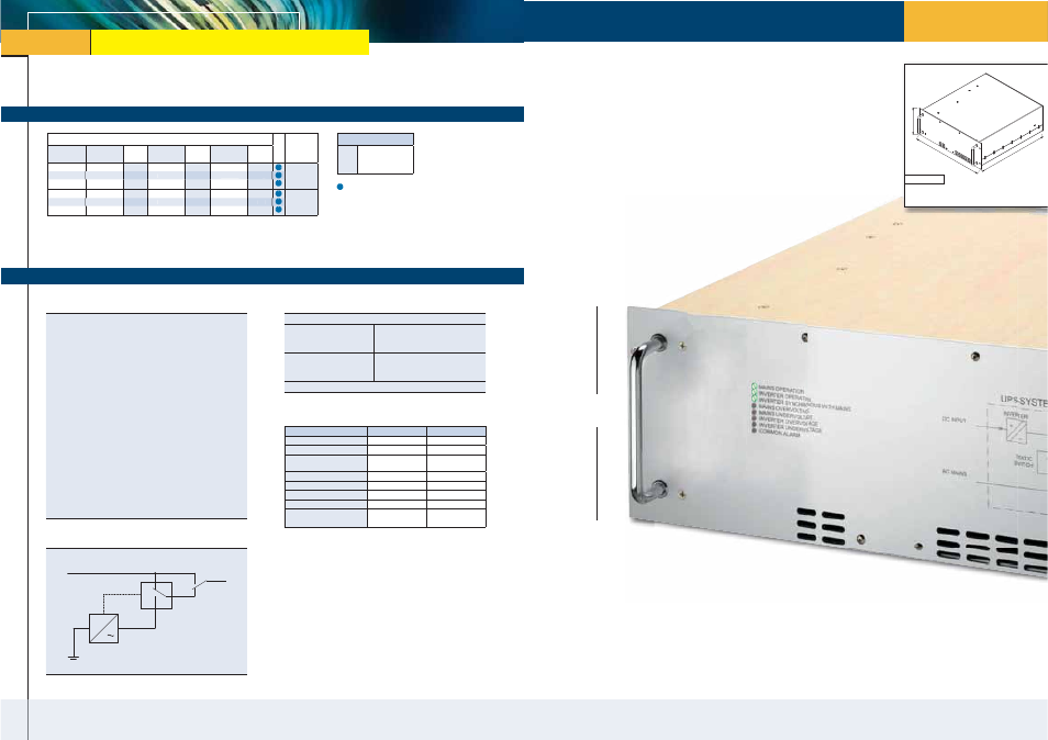
Static Switches
with 1-phase output from 0.8 to 10kVA
www.schaeferpower.de
Inverters
Series U
Uninterruptible Power Supply Systems
Input VDC
Cooling
Input /
Output
VAC
40 – 64
VDC
50 –80
VDC
Output
kVA
80 – 160
VDC
Output
kVA
160 – 320
VDC
Output
kVA
U 5436
U 5446
1.2
U 5256
U 5356
U 5456
1
1.2
2
U 5276
U 5376
U 5476
1
1.6
2.5
115
U 5438
U 5448
1.2
U 5258
U 5358
U 5458
1
1.2
2
U 5278
U 5378
U 5478
1
1.6
2.5
230
U 5356
1.2
U 5376
1.6
UPS
with 1-phase output from 1 to 2.5kVA
U 5358
1.2
U 5378
1.6
Series specific information
Function
The UPS provides uninterrupted power to a critical load, being supplied
either by mains or by batteries via the internal inverter.
In the automated function the supply of the priority input (mains) is
connected to the load. If the internal static switch detects deviation from
tolerance, it will transfer the load to the non-priority input (inverter).
When the supply of the priority input has returned to be within
parameters of voltage and frequency, the static switch reverses this
selection.
For adapting the UPS to different requirements, the priority for mains
or inverter operation can be selected externally via switch on the rear
side of the UPS. The UPS can also be inhibited either via opto-coupler or
via external relay contact for disconnecting the load. LEDs indicate the
mode of operation and / or the status of alarms. A potential-free relay
contact is given for common alarm.
Optionally, a manual bypass switch can be provided for connecting the
load directly to the mains while disconnecting the UPS or the batteries
in case of maintenance. For maximum flexibility the batteries (external)
can be specified according to the requirements on site and a suitable
battery charger (external) can be chosen from the Schaefer product
range.
UPS System
Input / Output
Transfer time
- mains to inverter (mains
priority) or inverter to
mains (inverter priority)
≤ ½ period, typically ¼ period
(including failure detection
time)
- return to mains (mains
priority) or return to
inverter (inverter priority)
practically no interruption
Transfer trigger
0.8 x U
nom
< voltage < 1.15 x U
nom
Indication of operation mode
4U
4U
19"
535 mm
Standard
approx. 20-28 kg
19“ Plug-in module
=
AC mains
Static Switch
Bypass Switch
AC output
(Load)
Inverter
Battery
Frequency Designation
.4
.5
.6
400 Hz
50 Hz
60 Hz
= incl. temperature
controlled fans
Green LED
Red LED
Mains operation
■
Inverter operation
■
Inverter synchronous with
mains
■
Mains over voltage
■
Mains under voltage
■
Inverter over voltage
■
Inverter under voltage
■
Common alarm
incl. potential free contact*)
■
*) U
max
= 250 VAC, I
max
= 3 A