LumaSense Technologies LumaSHIELD Controller Installation Guide: Spacer Disk User Manual
Instructions, Purpose, Lumasense technologies awakening your 6
www.lumasenseinc.com
©2013 LumaSense Technologies. All rights reserved.
LumaSense Technologies, Inc., reserves the right to change
the information in this publication at any time.
Americas and Australia
Sales & Service
Santa Clara, CA
Ph: +1 800 631 0176
Fax: +1 408 727 1677
Europe, Middle East, Africa
Sales & Service
Frankfurt, Germany
Ph: +49 69 97373 0
Fax: +49 69 97373 167
India
Sales & Support Center
Mumbai, India
Ph: +91 22 67419203
Fax: +91 22 67419201
China
Sales & Support Center
Shanghai, China
Ph: +86 133 1182 7766
Fax: +86 21 5877 2383
LumaSense Technologies
Awakening Your 6
th
Sense
LumaSHIELD Installation Guide - Spacer Disk-EN 514-0005-01 Rev. A 10/14/13
LumaSHIELD Installation Guide: Spacer Disk
Instructions
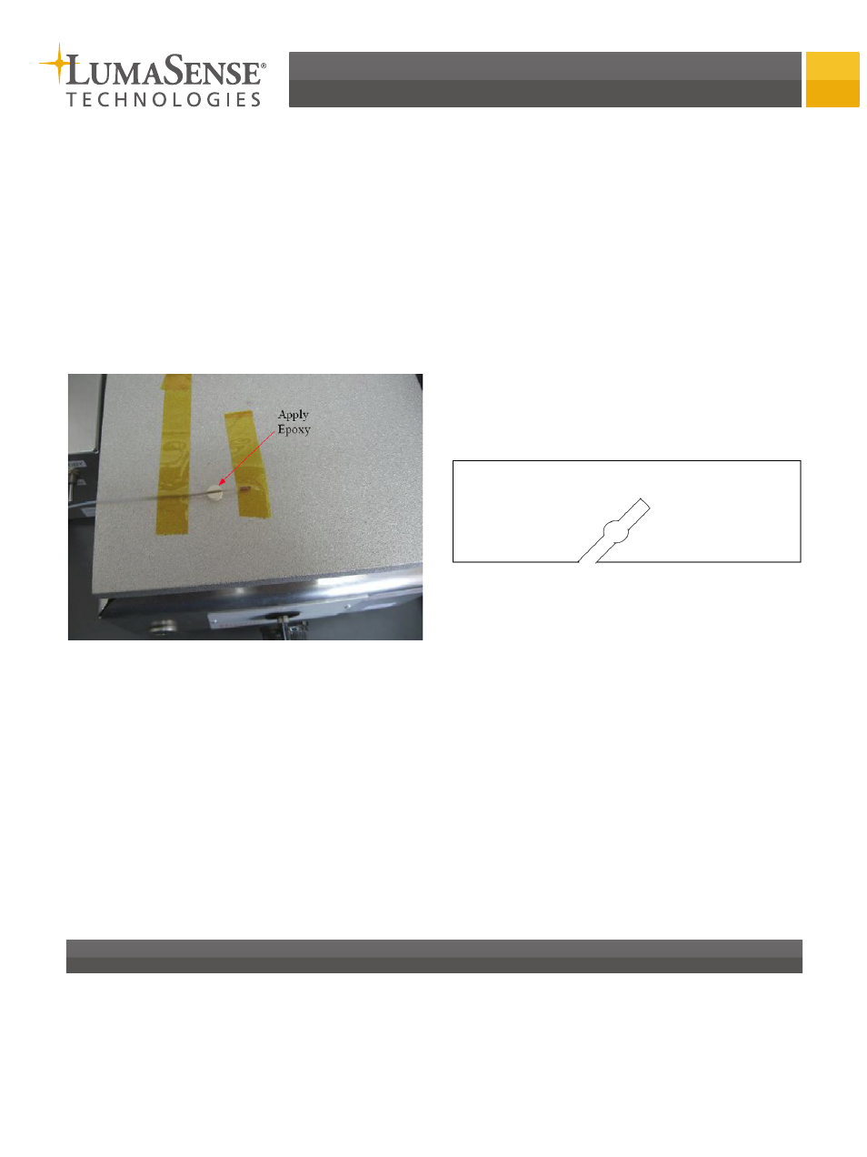
1. As shown in Figure 1, use polyimide tape to hold the
probe tip on a hot plate and put the spacer disk in
position. The location of the spacer disk depends on
the paper board structure (Refer to Figure 2).
2. Turn on power of the hot plate and warm the tem-
perature to around 93 °C.
3. Mix the two-part epoxy Aremco 631 with weight
ratio 1:1.
4. Use a piece of optical fiber or a toothpick to apply
the epoxy to the gap between the fiber and the
spacer disk as shown in Figure 1.
In case of epoxy flowing onto the hot plate, the
epoxy should be applied several times. For example,
apply once and cure it for 10 minutes and apply it
again until the epoxy filled the gap. After two hours
curing, the epoxy should be flush to the spacer disk
surface.
Figure 1: Spacer Disk Installation
Figure 2: Illustration of Paper Board
Purpose
This procedure is for installing the spacer disk onto the OTG-T (or OTG-T+) probe.