Johnson Level & Tool Mfg. 40-6200 User Manual
Page 3
3
3
• Check sheave side wobble and runout with a dial indicator. Stay within sheave manufacturer’s
guidelines.
• Install V-belts onto sheaves.
2. Compensate For Sheave Endwall Thickness Difference and Mount Laser and Targets
Using an inside caliper, measure the difference in endwall thickness between the two sheaves being
aligned. The measurement can be easily taken using the depth gauge end of the caliper. Place the butt end
of the caliper against the machined side face of the sheave and extend out the depth micrometer end of the
caliper until it contacts the side of the V-belt. Measure each sheave. If the difference is larger than 1/64”
.015”), then compensate for it using the targets, as explained in Grooved Targets section above.
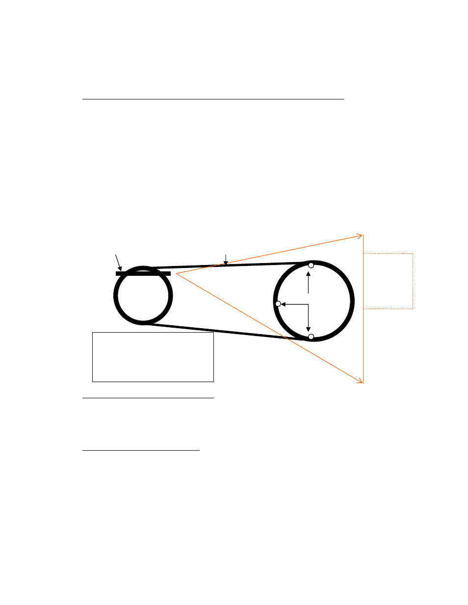
Mount the PowerLine™ Laser and targets as figured below. Note that the laser emitter can mount either on
the small sheave or the large sheave based on field conditions, however, it is preferable to mount it on the
smaller diameter sheave. Locate the PowerLine™ laser on the sheave rim so it is adjacent to the tight side
of the belt. Point the laser line so it projects along the tight side of the belt towards the companion sheave.
Mount the three targets on the companion sheave at the 12, 9, and 6 o’clock positions as shown. Make sure
each target’s magnetic bottom is extended full turn (1/16”) from flush when sheaves have equal thickness,
or, if you are compensating for sheave endwall thickness differences, make sure your adjustment is done
equally on all three targets.
3. Turning the PowerLine™ Laser on and off
Turn on the PowerLine™ laser by rotating the battery compartment end cap clockwise until the battery
circuit is energized. To turn off the laser, rotate the end cap counterclockwise and back off one full turn.
This will ensure laser does not energize inadvertently in storage. Spare batteries are included in the case.
4. Align Equipment Using Laser Targets
Align equipment until the projected laser line strikes the center of the groove on all three targets
simultaneously. This indicates excellent alignment. If the targets are not “aligned”, then the procedure for
correcting any misalignment is as follows:
The misalignment visible between the 12 o’clock and 6 o’clock targets indicates amount of “vertical”
angular and parallel misalignment. To correct this misalignment, loosen, shim, and tighten base bolts
and/or adjust the sheave axial positions on their respective shafts until “vertical" misalignment is corrected.
The laser line should now strike the target center of both the 12 o’clock and 6 o’clock targets.
Tight Side of Belt
PowerLine™ Laser
3 Targets
Visible
laser line is
projected
over target
area
Note:
It is preferable to place the
PowerLine™ laser onto the
smaller diameter sheave whenever
possible.