Johnson Level & Tool Mfg. 40-6200 User Manual
Page 2
2
2
Grooved Targets:
Three cylindrical grooved targets mount magnetically to the machined face of the companion pulley,
sheave, gear, etc. to be aligned. The targets track the position of the machined face relative to the laser
reference line emitted by the PowerLine™ laser. Excellent alignment is achieved when the laser line
strikes the center of the cylindrical grooves on all three targets simultaneously. Note, as a visual aid, when
the laser strikes the target center, it gives a brighter reflection than when the laser strikes the V shaped
sides.
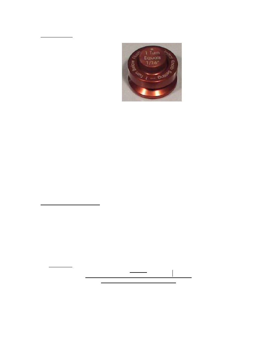
The offset between the center of the target groove and the magnetic bottom of the target is adjustable to
compensate for differences in pulley endwall thickness, belt wear, and groove wear. Turn the knurled knob
on the top of the target to make adjustments either up or down. As marked on top, one full turn of the knob
moves the target center up or down 1/16”. The initial knob setting is to extend the magnet bottom outward
from the bottom of the target bottom by one full turn (1/16” extended) so that the target center is 0.312”
away from the magnetic bottom. (See sketch on previous page.) For example, it is very common to find
pulleys of smaller diameter to have thinner rims than pulleys of larger diameter. During setup, measure this
difference using a dial caliper or equal means. Prior to mounting the targets, adjust the knobs of all three
target to compensate for the measured difference. When the laser is on the smaller pulley, the offset will be
reduced from initial setting of 0.312 by turning knob CCW.
Optional Belt Tension Testers:
Each PowerLine™ kit can include two (2) Kricket© belt tension testers. Combined, they cover a belt
tension range from 30 Lbs. to 300 pounds of tension. Separate instructions for these testers are included
with each Krikit© accessory. As a general rule of thumb, the deflection force tension specification given
by belt manufacturers must be multiplied by 16 to give proper Kricket© tension value. Use the Kricket©
tester based on this calculation. During tensioning, use the PowerLine™ laser to monitor and correct
alignment.
PowerLine™ Laser Sheave Alignment Tool Alignment and Tensioning Procedure
1. Prerequisites
Caution:
Lock out and tag out equipment before you start work.
Follow all applicable plant procedures.
• Inspect machinery bases and foundation for deterioration, looseness, and cracking.
• Check all base bolts for correct torque and eliminate any soft foot conditions.
• Remove belt guards as needed for access.
• Check sheaves and belts for wear. Replace as necessary.
• Check each shaft’s runout with a dial indicator. Excessive runout implies shaft or bearing problems.
Excellent alignment is achieved when the
laser line hits on center of the target groove.
This reference can be adjusted up or down to
compensate for sheaves with different
thickness by turning top knurled knob.
Initial knob setting is to
extend the magnet bottom
outward from the target
bottom by one full turn
(1/16”) so target groove
center is elevated 0.312”
off magnet bottom. Adjust
knob up or down from this.