Introduction, Specifications, Inspection of pump – Davey ISOSPEC CF Series ISO2858 Heavy Duty Industrial Centrifugal Pump User Manual
Page 2: Driving options, Installation location, Foundations, Suction piping, Discharge piping
~ 2 ~
Introduction
Thank you for purchasing a quality Davey product. It
is our commitment to satisfy our customers by offering
our very best service.
This manual contains instruction for installation,
operation and maintenance of ISOspec
®
CF
bareshaft, single stage, non-self priming, centrifugal
pumps. Therefore, please read it carefully before use
to obtain a long satisfying service life of the purchased
unit.
Davey ISOspec
®
CF bareshaft centrifugal pumps are
designed with high efficiency and low maintenance
features.
Specifications
Model designation (example) :-
CF 200×150-500
Nominal dia. of impeller (mm)
Dia. of outlet (mm)
Dia. of inlet (mm)
Series code of pump
Inspection of Pump
Always check on receipt of delivery you have
received the correct pump unit. To identify, see above
specifications and label below. Check correct motor
kW & speed on motor nameplate (attached to motor)
prior to installation.
Driving Options
Your ISOspec
®
pump can be driven by a variety of
means. The best option is to direct drive via a suitable
coupling. If you must belt drive your ISOspec
®
pump,
lower speed (rpm). Limits may apply - see below:
Pump Size
Direct
Belt
50x32-160
3600 2900
65x50-160
3600 2900
80x65-160
3600 2900
100x80-160
3600 2850
50x32-200
3600 2900
65x40-200
3600 2900
80x50-200
3600 2900
100x65-200
3600 2250
125x100-200
3600 2060
65x40-250
3600 2480
80x50-250
3600 2050
100x65-250
3600 2180
125x100-250
3000 1620
150x125-250
2350 1440
65x40-315
3000 1800
80x50-315
3000 1800
100x65-315
3000 1450
125x100-315
3000 1380
150x125-315
2350 1420
200x150-315
1800 1150
250x200-315
1800 920
125x80-400
2350 1450
125x100-400
2350 1240
150x125-400
2350 1060
200x150-400
1800 920
125x100-500
1800 1240
150x125-500
1800 1060
200x150-500
1800 920
250x200-400
1800 920
Installation Location
It is important to select a site as close to the
liquid source as possible. When a suction lift is
unavoidable, install the pump as near to the water
level as possible (see suction piping). You should
always check the maximum permissible lift of the
pump from its performance curve.
Foundations
The pump unit should be mounted on a foundation
that is substantial enough to withstand the weight of
the unit & large enough to accommodate all mounting
feet so they can be securely fixed to avoid movement.
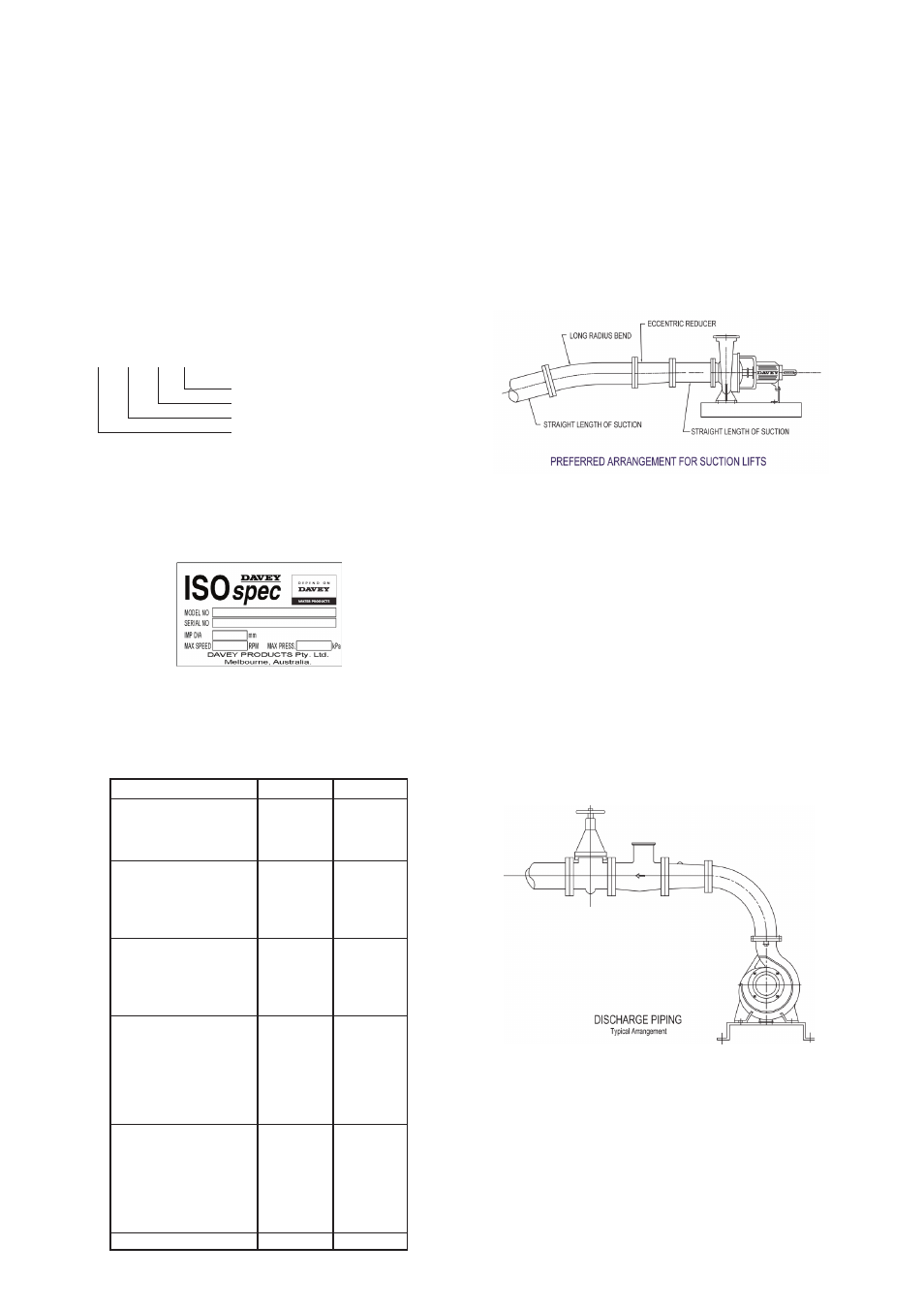
Suction Piping
All fittings & suction piping should be free of air leaks.
When a suction lift or long suction lengths are
unavoidable, consideration should be given to over
sizing the suction line to reduce suction losses. On
suction lifts a foot valve will be required, sized equal to
the suction line size. For applications on creek beds
or dams, please install a foot valve & strainer, well
submerged below the surface, to reduce whirlpools
& air inclusion. Air inclusion can result in cavitation
reducing the pump performance & eventually
destroying the pump or its components.
Long radius bends should be installed & a straight
length of piping equal to 2.5, the impeller diameter,
should be observed. Supporters should be equipped
to the inlet pipeline and outlet pipeline to avoid the
pump flange bearing too much tension force.
Discharge Piping
Discharge piping must be selected of a size that
would equal the discharge of the pump. For long
discharge lengths, consideration should be given to
oversize to minimize discharge losses reducing flow.
Talk to your nearest Davey dealer to calculate all
system losses. To avoid air pockets in discharge
lines at high points, vent cocks may be required to
release air blocks accumulated within the system. Air
pockets may affect the performance of the pump. A
throttling valve should be installed in the discharge
line to ensure the pump works within the performance
curve.