0 maintenance, Caution – Condec UVC1010 User Manual
Page 6
4
UVC1000/UVC1010 Operation and Maintenance Manual
3.0
Maintenance
3.1
Troubleshooting
3.2
Test and Maintenance Procedures
This section outlines the test and mechanical repair procedures for the UVC1000/UVC1010 Vacuum
Generator/Pressure Controller. The repair procedures cover the major components and subassemblies which are
critical to the proper functioning of the UVC1000/UVC1010 and that will likely need periodic maintenance over
the life of the unit.
Only those persons who are formally trained as skilled technicians should attempt to repair these
units. Although some mechanical sub-assemblies could be replaced without venting line pressure, it
is not recommended. All safety precautions should be observed.
3.2.1
Test Procedure
Tools required:
Snoop
®
, liquid leak gas detector (PN 64781)
1. Remove cover from its enclosure as described in Section 3.2.2, and place on a bench top.
NOTE:
Do not remove Input hose.
2. Verify MODE SELECT is on PRESSURE, turn knob to the left.
3. Connect shop air to the unit, at the INPUT, on the rear of the unit.
NOTE:
The air pressure source used must have a vent valve and be regulated to provide a maximum output of 160
PSIG.
4. Pull out the PRESSURE LIMIT CONTROL, until you hear a click. Turn the knob clockwise until you
get a reading of 100 PSI. Push knob inward.
5. Check all pipe connections for leaks by using Snoop
®
.
6. Turn the MODE SELECT to VACUUM mode slowly.
7. Verify the vacuum gage is reading -28.5 to 29 psi.
NOTE:
The air pressure source and PRESSURE LIMIT CONTROL may have to be increased to obtain reading
(maximum 160 PSIG).
8. Install cover on its enclosure as described in Section 3.2.2.
3.2.2
UVC1000/UVC1010 Cover - Removal and Installation
Tools required:
Phillips screwdriver
UVC1000 Cover Removal:
1. Vent input line pressure and remove input and port hoses.
2. Pull out the PRESSURE LIMIT CONTROL knob, until you hear a click. To close regulator, rotate knob
counter-clockwise, until it stops. Push knob inward.
3. Loosen and remove the six screws (PN 14839) that secure the cover to the enclosure.
4. Lift and remove the cover.
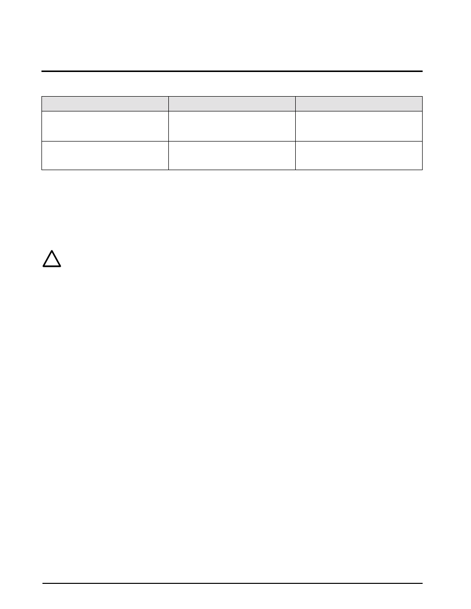
Symptom
Problem
Remedy
Pressure Limit Monitor gauge or Vacuum
Monitor gauge slowly decreases over
time
Leak in system
Check all compression and pipe fittings
with soap solution or Snoop
®
(PN
64781)
Applicable gauge does not respond
when Pressure Limit Control knob is
turned
No regulator control
Try other mode of operation. If o.k,
replace gauge, otherwise replace
Pressure Limit Control regulator
Table 3-1. UVC1000/UVC1010 Troubleshooting
!
Caution