Installation steps, Step 1 important notice step 2 step 3 – Burcam 300530 THERMOPLASTIC BASE COLUMN SUMP PUMP 1/3HP 115V User Manual
Page 2
Material required for
sump pump application
• Desired length of 1 1/2” ABS pipe.
• Elbows and fittings to run discharge pipe.
• ABS cimentz
• 1 1 1/2” ABS coupling to connect the pipe
to the check valve.
• 1 vertical check valve (350353).
APPLICATION
• This domestic sump pump is suitable for application where the
total vertical distance (head) does not exceed 15’. It is designed
as an economic and efficient means of protecting homes
agains water damage through seepage, where there is no natural
drainage.
• Capacity: 3000 GPH/ 5’ 2400GPH/10’ 1500GPH/15’
Locate the rod, the float and the rubber washers in the pump carton. Secure rod’s quide to pump’s
column. Push the rod through the rod guide, then push a rubber washer about six inches from top rod
end. Insert rod end through the top mount switch opening and place the second rubber washer over the
top rod end. Thread the float into the bottom rod end about six to eight turns. Depth of pumping level may
be adjusted by changing the position of the lower rubber rod washer.
Install the required (350353) check valve in the 1 1/4” discharge of the pump’s base. Thread in tightly.
Using 1 1/2” ABS coupling and ABS pipes, connect the discharge line to the check valve, and run it to the
desired waste location throught the basement wall of your house. Otherwise, drain hose kits are available
(350354). You may also connect a kit to the check valve with a clamp and run the pipe to the same
location. Be advised that restriction in these kits is important and increase the head of the discharge line.
Position the sump pump in centre of the sump pit (18” diameter X 25” deep). Plug the pump motor three
prong plug/cord into a grounded electrical outlet. Fill the sump pit with water to check pump operation.
Pump should start automatically when the switch lever is activated by the rubber washer and stop when
the water has been discharged and the float returns to the bottom of the sump pit.
Please note before you proceed with the installation of this product that the manufacturer’s
guideline
has to be respected. Failure to comply may void your warranty.
The following are minimum requirements in order to protect your residence from flooding. It is a small investment but it is
your personal responsibility to protect your home, family and valuables. Failure to comply with the following requirements
may also void your warranty:
• Two (2) pumps
have to be installed in the sump pit. The first pump as a primary pump and the second pump as the
backup unit.
• Burcam alarm system model 450454
has to be installed to advise you of any malfunctions.
• As sump pumps are electrically powered and activated so to prevent flooding, a Burcam battery powered back up pump
model 300403
has to be installed to evacuate the water.
Pump selection, proper and adequate installation are a must to comply with local by-laws and need to be adhered to.
STEP 1
IMPORTANT NOTICE
STEP 2
STEP 3
FRICTION LOSS IN PIPE NOT INCLUDED
NOTICE
This unit is not designed for applications involving salt
water or brine. Use with salt water or brine will void
warranty.
This product has been designed as a
dewatering pump for flood protection in a
residential home. The application of this
product is for permanent installation. Do not
use this pump to pump liquids (water)
in excess of 100 degrees F.
To the end consumer
If you have any problems with the product, before
advising the store, where you’ve purchased the pump,
please contact us at 514 337-4415 , and ask for our
sales department, and they will be pleased to help you
with any questions you might have, concerning your
installation.
INSTALLATION STEPS
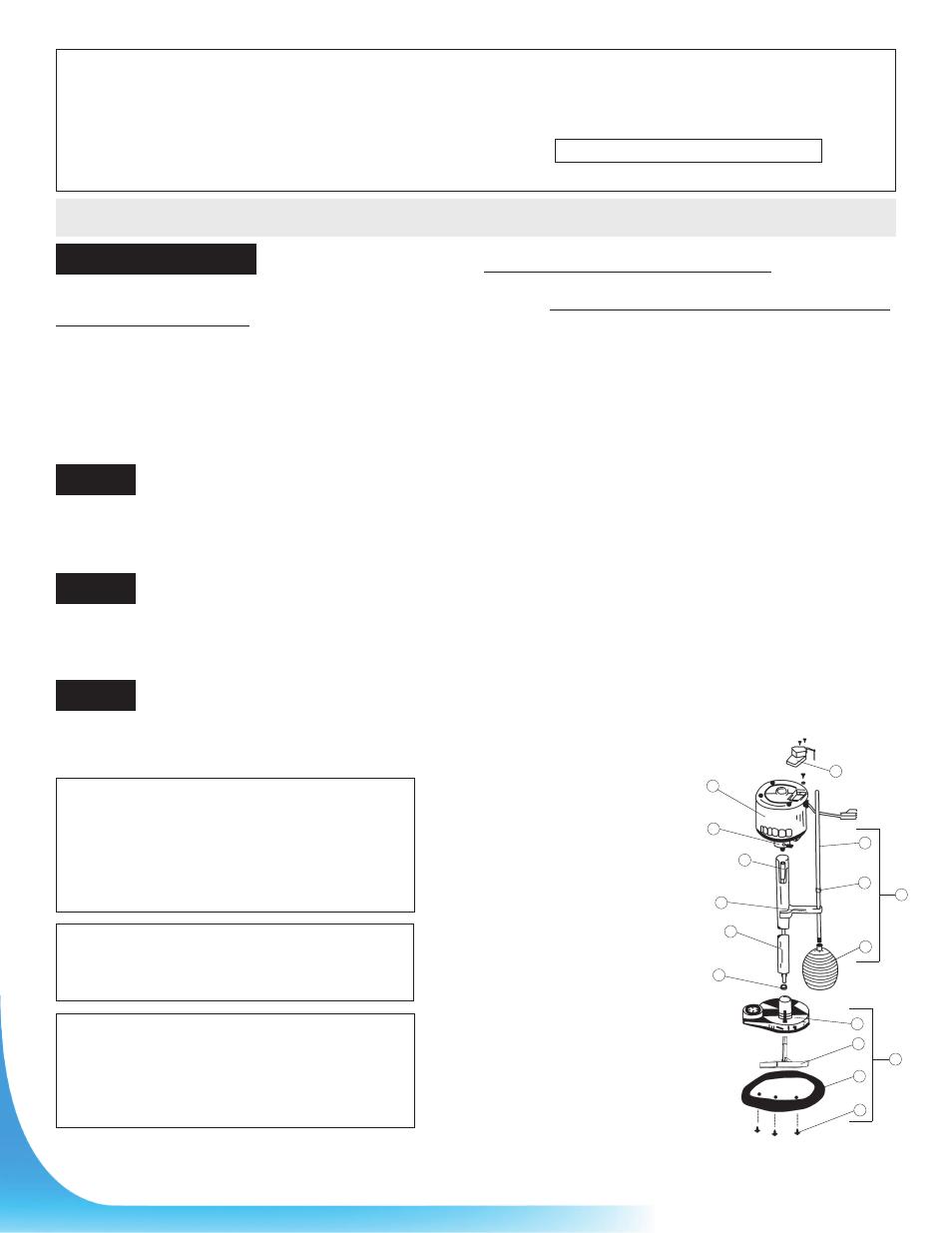
REPAIR PARTS
REF. PART
DESCRIPTION
1
350445
Top mount switch
2
350350A 1/3 HP 115V motor
3
350453
PVC main shaft with coupling
4
350450
Float rod
5
350447
Rubber stop (2)
6
350449
Float
7
350443
Float guide
8
350444
PVC column
9
350200
Volute suction
10
350202
Impeller
11
350201
Round base plate
12
350460
Base plate screws (12)
13
350446.1 Float/rod assembly
14
350468
Base assembly
15
350456
Motor bolts (3)
16
350461
Snap ring
15
16
1
2
3
4
8
6
7
5
9
10
11
12
14
13