Air pressure tank installation – Burcam 105 Series Submersible Deep Well Pumps or SUB-PACS v.2 User Manual
Page 9
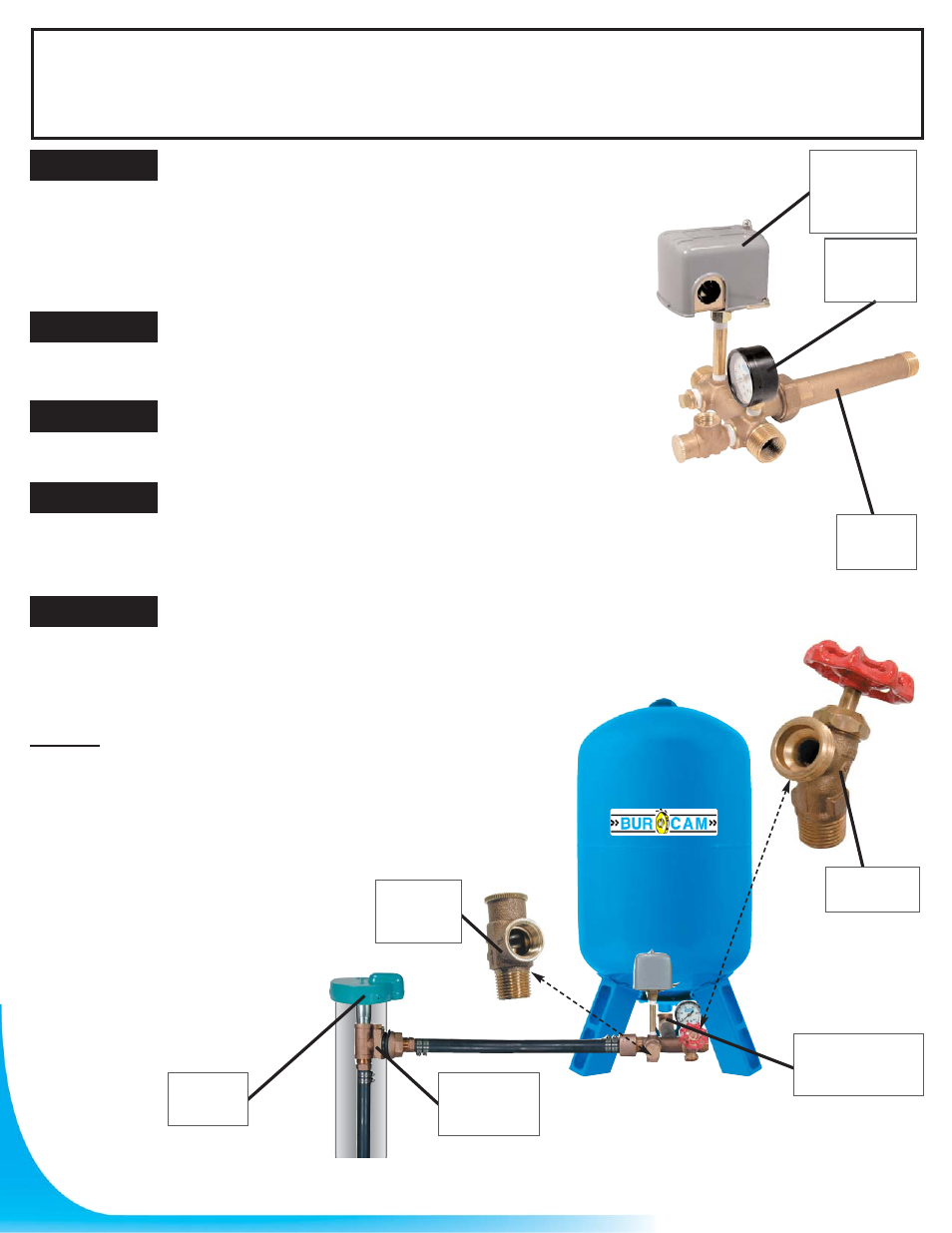
AIR PRESSURE TANK INSTALLATION
“Free-Standing” type tanks have to be installed offset
from your pump, and in the discharge line coming from
your pump’s
discharge connection (either a jet or submersible
pump). Turn your tank on its side and install a galvanized
90º elbow (1” or 1 1/4” as per needed) to the
inlet-outlet connection, using an ample supply of
teflon tape on the threads.
Determine the position or location in which you wish to
leave your tank permanently. Leave ample room to make
your tank connections.
Screw the long end of the tank “T” (650651 or 650662) to
the tank elbow’s using teflon tape. If required, install a
reducing adaptor 1 1/4” - 1” NPT.
Install a pressure gauge (750769) and a pressure switch (750776S)
(with a 1/4” X 3” nipple) in the 1/4” opening of the tank “T”. Then, install
a drain valve (650659) and a safety relief valve (1501162) in the 1/2”
opening of the tank “T”.
In the service line leading from the tank “T”, we recommend that you
install a service gate valve to allow you to shut-off you water supply in
the case of repairs to the home’s water fixtures.
STEP 1
STEP 2
STEP 3
STEP 4
STEP 5
NOTES:
The above parts are recommended. Use teflon tape on all treads. Use a pipe
wrench to tighten each piece adequately.
The tank size is very important. Ensure that you select a tank which will meet
your requirements. Several tank models are
available (larger one is always preferable).
9
Pressure
relief valve
#150162
90
0
galvanized
or brass elbow
Drain valve
#650659
Pitless
adaptor
#150155
Well seaL
#750871
L.O.P
Pressure
switch
#150159S
Pressure
gauge
#750769
“T”
tank
#650662