PULS MLY02.100 User Manual
Page 3
MLY Instruction Manual for Redundancy Modules
MLY Bedienungsanleitung für Redundanzmodule
Product Description
The reliability of the DC voltages can be increased by using redundant systems. To achieve
redundancy, one extra power supply must be installed in order to deliver the required current in
case one power supply in the system fails. Each individual power supply must be isolated from the
others with a redundancy module. These have decoupling diodes included and are equipped with
two input and one output channels. They can be used to build 1+1 and N+1 redundant systems.
Both units listed in this instruction sheet are electrically the same and differ only in the type of
terminals and the optical appearance. The MLY10.241 is a perfect fit for the MiniLine-2 power
supplies, while the MLY02.100 is suitable for the MiniLine power supplies.
Gerätebeschreibung
Die Zuverlässigkeit von DC-Spannungen kann durch redundante Systeme erhöht werden. Um
eine Redundanz zu erreichen, muss ein zusätzliches Gerät in „Reserve“ installiert werden, das
dann den nötigen Laststrom zur Verfügung stellt, wenn ein Gerät im System ausfällt. Die
einzelnen Geräte müssen mit Redundanzmodulen entkoppelt sein. Diese beinhalten
Entkopplungsdioden und haben zwei Eingänge und einen Ausgang und können zum Aufbau von
N+1 oder 1+1 redundanten Systemen verwendet werden.
Die beiden hier aufgeführten Geräte sind elektrisch gleichwertig und unterscheiden sich nur in der
Klemmenart und in der optischen Ausführung. Das MLY10.241 ist den Geräten der MiniLine-2
Serie angepasst, während das MLY02.100 für Geräte der MiniLine Serie gedacht ist.
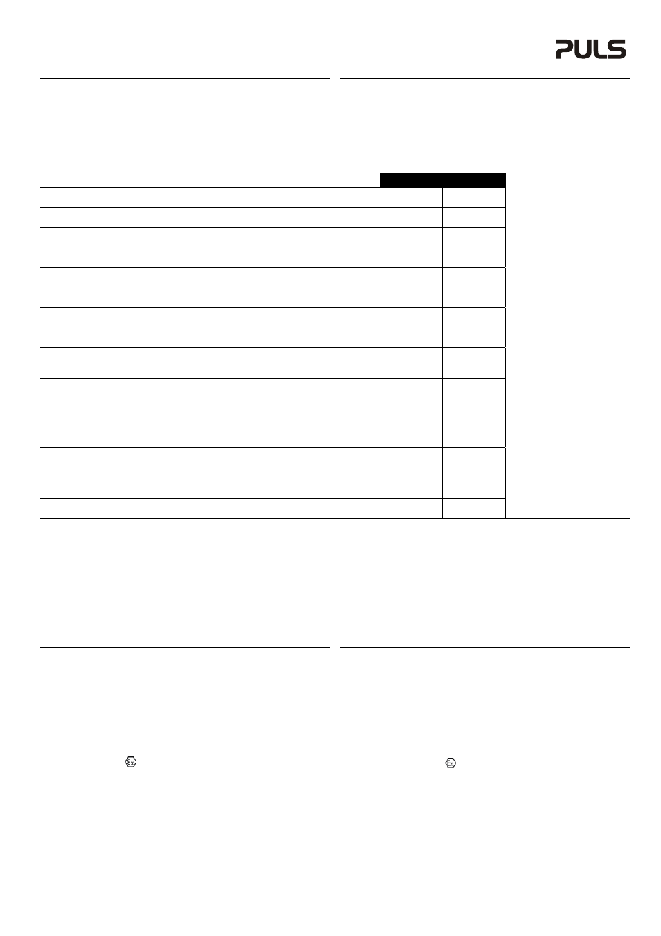
Technical Data
1)
Technische
Daten
1)
MLY02.100
MLY10.241
Input Voltage
Eingangsspannung
nom.
DC 12-48V ±25%
DC 12-48V ±25%
Input Voltage Range
Eingangsspannungsbereich
-
9-60Vdc
9-60Vdc
Output Current
2)
Normal Mode Ausgangsstrom
2)
Normalbetrieb
nom.
10A
10A
Overload, Short-circuit
Überlast, Kurzschluss
max.
16A
3)
16A
3)
Input Current
2)
1+1 Redundancy Mode Eingangsstrom
2)
1+1 Redundanz Modus
nom.
2x 8A
2x 8A
N+1 Redundancy Mode
N+1 Redundanz Modus
nom.
2x 5A
2x 5A
Peak Input Current (per input) Eingangsspitzenstrom (pro Eingang)
max.
125A for 10ms
125A for 10ms
Reverse Current
4)
(per input) Rückwärtsstrom
4)
(pro Eingang)
max.
0.6mA
0.6mA
Decoupling Element
Entkopplungselement
-
Diode
Diode
Voltage Drop
5)
(Input to Output) Spannungsabfall
5)
(Eingang zu Ausgang)
typ.
900mV
900mV
Power Losses
5)
at full load Verlustleistung
5)
bei Volllast
typ.
9W
9W
at no load
im Leerlauf
typ.
0W
0W
Low-Input-Voltage Alarm Contacts Eingangsspannungsüberwachungsrelais
-
no / nein
no / nein
Operational Temperature Range Betriebstemperaturbereich
nom.
-40°C - +70°C
-40°C - +70°C
Output Derating
Ausgangsstromrücknahme
+60°C to +70°C
0.25A/°C
0.25A/°C
Storage Temperature Range
Lagertemperaturbereich
nom.
-40°C - +85°C
-40°C - +85°C
Humidity
6)
Feuchte
6)
IEC 60068-2-30
5 – 95% r.H.
5 – 95% r.H.
Vibration Schwingen
IEC 60068-2-6
2g
2g
Shock Schocken
IEC 60068-2-27 30g 6ms, 20g 11ms 30g 6ms, 20g 11ms
Degree of Pollution (non-conductive) Verschmutzungsgrad
(nicht leitend)
EN 50178 / IEC 62103
2
2
Degree of Protection
Schutzart
EN 60529
IP20
IP20
Class of Protection
Schutzklasse
IEC 61140
III
III
Over-Temperature Protection
Übertemperaturschutz
OTP
no / nein
no / nein
Reverse Input Polarity Protection Eingangsverpolschutz
-
yes / ja
yes / ja
Penetration Protection
Fremdkörper Eindringschutz
max.
2.5mm
2.5mm
Return Voltage Resistance
7)
Rückspeisefestigkeit
7)
max.
200Vdc
200Vdc
Isolation Against Housing
Isolationsfestigkeit gegen Gehäuse
min.
500Vac, 5MOhm
500Vac, 5MOhm
Quick-Connect Spring-Clamp Terminals
Schnellanschluss Federkraftklemmen
-
yes / ja
-
Screw Terminals
Schraubklemmen
-
-
yes / ja
Dimensions
8)
(WxHxD) Abmessungen
8)
(BxHxT)
nom.
45x75x91mm
45x75x91mm
Weight Gewicht
max.
140g, 0.31lb
140g, 0.31lb
Approvals Zulassungen
-
9)
9)
Limited Warranty
Gewährleistung
Years / Jahre
3
3
1) All parameters are specified at 24Vdc input voltage, nominal output current, 25°C ambient
and after a 5 minutes run-in time unless otherwise noted.
2) 50% higher currents up to 5s are allowed. The average (RMS) current is not allowed to
exceed 103% of the nominal current if repetitive pulses occur.
1+1 and N+1 Redundancy modes are explained in figures 1 to 2.
3) Ensure that the continuous output current does not exceed this value. Check the short-circuit
current of power sources. Do not use power sources which can deliver higher currents.
4) Over the entire temperature range.
5) At nominal output current and symmetrical input currents. See figure 4.
6) Do not energize while condensation is present.
7) Loads such as decelerating motors and inductors can feed voltage back to the output of the
redundancy module. The figure represents the maximum allowed feed back voltage.
8) Depth without DIN-rail and connection terminals.
9) See datasheet or markings on the unit.
1) Alle Werte gelten bei 24Vdc Eingangsspannung, Nennausgangsstrom, 25°C Umgebungs-
temperatur und nach einer Aufwärmzeit von 5 Minuten, wenn nichts anderes angegeben ist.
2) 50% höhere Ströme sind bis zu 5s erlaubt. Der Mittelwert (RMS) des Stromes darf 103% des
Nennwertes nicht überschreiten, falls wiederholende Pulse auftreten.
1+1 und N+1 Redundanzmodus sind in den Bildern 1 bis 2 erklärt.
3) Der Dauerausgangsstrom darf auch im Fehlerfall diesen Wert nicht überschreiten. Verwenden
Sie keine Stromversorgungen, die in der Summe höhere Ströme liefern können.
4) Über den gesamten Arbeitstemperaturbereich.
5) Bei Nennausgangsstrom und symmetrischen Eingangsströmen. Siehe auch Bilder 4.
6) Nicht betreiben, solange das Gerät Kondensation aufweist.
7) Bremsende Motoren oder Induktivitäten können Spannung zum Ausgang des
Redundanzmoduls rückspeisen. Der Wert gibt die max. zulässige Rückspeisespannung an.
8) Tiefe ohne DIN-Schiene und Anschlussklemmen.
9) Siehe Datenblatt oder Prüfzeichen auf dem Gerät.
Installation
Use DIN-rails according to EN 60715 or EN 50022 with a height of 7.5 or 15mm. Mounting
orientation must be output terminals on bottom and input terminals on the top. For other
orientations see datasheet. Do not obstruct air flow as the unit is convection cooled. Ventilation
grid must be kept free of any obstructions. The following installation clearances must be kept
when power supplies are permanently fully loaded:
Left / right: 0mm (or 15mm in case the adjacent device is a heat source)
40mm on top, 20mm on the bottom of the unit.
The external circuitry of all terminals (including signalling contacts) must meet the safety
requirements stipulated by IEC/EN/UL 60950-1: SELV.
Use in hazardous location areas
Units which are marked with "Class I Div 2" are suitable for use in Class I Division 2 Groups A, B,
C, D locations.
Units which are marked with
II 3G Ex nA IIC T4 Gc are suitable for use in Group II Category 3
(Zone 2) environments and are evaluated according to EN 60079-0:2009 and EN 60079-15:2010.
WARNING EXPLOSION HAZARDS!
Substitution of components may impair suitability for this environment. Do not disconnect the unit
unless power has been switched off or the area is known to be non-hazardous. A suitable
enclosure must be provided for the end product which has a minimum protection of IP54 and fulfils
the requirements of the EN 60079-15:2010.
Installation
Geeignet für DIN-Schienen entsprechend EN 60715 oder EN 50022 mit einer Höhe von 7,5 oder
15mm. Der Einbau hat so zu erfolgen, dass sich die Eingangsklemmen oben und die
Ausgangsklemmen unten befinden. Für andere Einbaulagen siehe Datenblatt. Luftzirkulation nicht
behindern! Das Gerät ist für Konvektionskühlung ausgelegt. Es ist für ungehinderte Luftzirkulation
zu sorgen. Folgende Einbauabstände sind bei dauerhafter Volllast einzuhalten:
Links / rechts: 0mm (oder 15mm bei benachbarten Wärmequellen)
Oben: 40mm, unten 20mm vom Gerät.
Die externe Beschaltung aller Klemmen (einschließlich Signalklemmen) muss den Anforderungen
an SELV Kreisen nach IEC/EN/UL 60950-1 genügen.
Betrieb in explosionsgefährdeter Umgebung
Geräte, die mit "Class I Div 2" gekennzeichnet sind, sind für den Einsatz in Klasse I Division 2
Gruppen A,B,C,D Umgebung geeignet.
Geräte, welche die Kennzeichnung
II 3G Ex nA IIC T4 Gc tragen, sind nach EN 60079-0:2009
und EN 60079-15:2010 getestet und können in Gruppe II, Kategorie 3 (Zone 2) Umgebungen
verwendet werden.
ACHTUNG EXPLOSIONSGEFAHR! Veränderungen am Gerät können die Tauglichkeit für diese
Umgebung beeinträchtigen. Anschlüsse nicht abklemmen solange Spannung anliegt oder die
Umgebung als explosionsgefährlich gilt. Das Gerät muss mindestens in ein IP54 Gehäuse,
welches den Anforderungen der EN 60079-15:2010 entspricht, eingebaut werden.