PULS ML15.051 User Manual
Page 4
ML15/ML30 Instruction Manual for Power Supplies
ML15/ML30 Bedienungsanleitung für Stromversorgung
Terminals and Wiring
Use appropriate copper cables that are designed for a minimum operating temperature of:
60°C for ambient temperatures up to 45°C,
75°C for ambient temperatures up to 60°C and
90°C for ambient temperatures up to 70°C.
Follow national installation codes and regulations! Ensure that all strands of a stranded wire enter
the terminal connection! Ferrules are allowed. Unused terminal must be closed.
Solid
wire
0.5-6mm
2
Stranded
wire
0.5-4mm
2
American wire gauge
AWG20-10
Max. wire diameter:
2.8mm (includes ferrules)
Wire stripping length
7mm / 0.28inch
Tightening torque
1Nm / 9lb.inch
Screw driver:
3.5mm slotted or Philips No 2
Anschlussklemmen und Verdrahtung
Verwenden Sie geeignete Kupferkabel, die mindestens für:
60°C bei einer Umgebungstemperatur bis zu 45°C,
75°C bei einer Umgebungstemperatur bis zu 60°C und
90°C bei einer Umgebungstemperatur bis zu 70°C zugelassen sind.
Aderendhülsen sind erlaubt. Nationale Bestimmungen und Installationsvorschriften beachten!
Achten, dass keine einzelnen Drähte von Litzen abstehen. Nichtbenutzte Klemmen schließen.
Starrdraht
0,5-6mm
2
Litze
0,5-4mm
2
AWG
AWG20-10
Maximaler Drahtdurchmesser:
2,8mm (incl. Aderendhülsen)
Abisolierlänge
7mm
/
0,28inch
Anzugsdrehmoment
1Nm / 9lb.inch
Schraubendreher:
Schlitzschraubendreher 3,5mm oder Philips No 2
CE Marking
CE mark is in conformance with EMC directive 2004/108/EC, the low-voltage directive (LVD)
2006/95/EC and the RoHS directive 2011/65/EU.
EMC Immunity: EN 61000-6-1, EN 61000-6-2
EMC Emission EN 61000-6-3, EN 61000-6-4, FCC Part 15 Class B
CE Kennzeichnung
Das CE Zeichen ist angebracht und erklärt die Erfüllung der EMV Richtlinie 2004/108/EG, der
Niederspannungsrichtlinie 2006/95/EG und der RoHS Richtlinie 2011/65/EU.
Störfestigkeit: EN 61000-6-1, EN 61000-6-2
Störaussendung: EN 61000-6-3, EN 61000-6-4, FCC Part 15 Klasse B
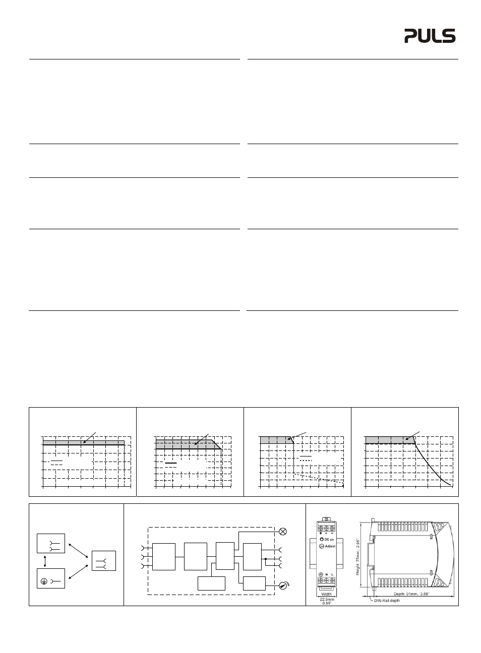
Output- and Overload Characteristic
(see Fig. 1 to 4)
The units are overload, no-load, short-circuit proof.
ML15: Above the rated output current, the output voltage will decrease as a result of the output
current limitation. In case of excessive overloads, the unit will switch off and will make
automatically start-up attempts (Hiccup-Mode). Similar behavior can occur with loads
having large input capacitors included. See also datasheet for details.
ML30: Above the rated output current, the output voltage will decrease as a result of the output
current limitation. The current flows continuously. No hiccup or shut-down behaviour.
Ausgangs- und Überlastverhalten
(siehe Bild 1 bis 4)
Die Geräte sind leerlauf-, überlast- und kurzschlussfest.
ML15: Wird der Nennausgangsstrom überschritten, sinkt die Ausgangsspannung als Folge der
strombegrenzenden Wirkung des Gerätes. Bei extremer Überlastung schaltet das Gerät ab
und macht automatische Startversuche (Hiccup-Mode). Ähnliches Verhalten kann auch bei
Lasten mit großen Eingangskapazitäten auftreten. Siehe auch Informationen im Datenblatt.
ML30: Wird der Nennstrom überschritten, sinkt die Spannung aufgrund der Strombegrenzungs-
eigenschaft. Der Strom fließt ununterbrochen weiter, kein Hiccup oder Abschaltverhalten.
Dielectric Strength
(see Fig. 5)
The output voltage is floating and separated from the input according to SELV (IEC/EN 60950-1)
and PELV (EN 60204-1, EN 50178; IEC 62103, IEC 60364-4-41) requirements. Type and factory
tests are conducted by the manufacturer. Field tests may be conducted in the field using the
appropriate test equipment which applies the voltage with a slow ramp (2s up and 2s down).
Connect all phase-terminals together as well as all output poles before the test is conducted.
When testing, set the cut-off current settings to the value in the table below.
A B
C
Type Test (60s)
2500Vac
3000Vac
500Vac
Factory Test (5s)
2500Vac
2500Vac
500Vac
Field Test (5s)
2000Vac
2000Vac
500Vac
Cut-off current setting
>6mA
>6mA
>1mA
Isolationsfestigkeit
(siehe Bild 5)
Die Ausgangsspannung hat keinen Bezug zur Erde oder Schutzleiter und ist zum Eingang nach
den SELV (IEC/EN 60950-1) und PELV (EN 60204-1, EN 50178, IEC 62103, IEC 60364-4-41)
Standards getrennt. Typ- und Stückprüfungen werden beim Hersteller durchgeführt. Wieder-
holungsprüfungen dürfen mittels geeigneten Prüfgenerators mit langsam (2s) ansteigenden und
abfallenden Spannungsrampen in der Anwendung erfolgen. Vor den Tests sind alle Phasen wie
auch alle Ausgangspole miteinander zu verbinden. Während der Tests darf die Strom-
Abschaltschwelle nicht kleiner als der in der Liste angegebene Wert sein.
A B C
Typprüfung (60s)
2500Vac
3000Vac
500Vac
Stückprüfung (5s)
2500Vac
2500Vac
500Vac
Wiederholungsprüfung (5s)
2000Vac
2000Vac
500Vac
Strom- Abschaltschwelle
>6mA
>6mA
>1mA
Fig. 1 / Bild 1
ML15.051: Output Characteristic /
Ausgangskennlinie, typ.
Fig. 2 / Bild 2
ML15.121: Output Characteristic /
Ausgangskennlinie, typ.
Fig. 3 / Bild 3
ML15.241: Output Characteristic /
Ausgangskennlinie, typ.
Fig. 4 / Bild 4
ML30.241: Output Characteristic /
Ausgangskennlinie, typ
Output Voltage
0
0
1
2
6V
3
4
5
3.5A
2.5
1.5
0.5
2.0
1.0
3.0
Adjustment
Range
Output Current
Continuous
Hiccup Mode
Output Voltage
0
0
2
4
6
16V
8
10
12
2.0A
1.0
0.6
0.2
1.4
0.8
0.4
1.2
14
1.8
Adjustment
Range
Output Current
Continuous
Hiccup Mode
Output Voltage
0
0
4
8
12
28V
16
20
24
2A
1.0
0.6
0.2
1.4
0.8
0.4
1.2
1.6 1.8
Adjustment
Range
Output Current
Continuous
Hiccup Mode
Output Voltage
0
0
0.8
1.6
4
8
12
28V
16
20
24
2.8A
2.0
1.2
0.4
2.4
Adjustment
Range
Output Current
Fig. 5 / Bild 5
Insulation / Isolation
Fig. 6 / Bild 6
Functional Diagram / Funktionsschaltbild
Fig. 7 / Bild 7
Physical Dimensions / Abmessungen
A
C
N
L
Input
Earth, PE
Output
-
+
B
Input Fuse
&
Input Filter
L
N
Output Over-
Voltage
Protection
Input
Rectifier
&
Inrush
Limiter
Power
Converter
Output
Voltage
Regulator
+
-
-
Output
Filter
V
OUT
DC
on
PE
PU-371.012.00-10B