PULS YR2.DIODE User Manual
Page 4
YR: Redundancy Modules Instruction Manual
YR: Bedienungsanleitung für Redundanzmodule
Footnotes of the Specification Tables:
1) All parameters are specified at 24V input voltage (48V for the YR40.482), nominal output
current, 25°C ambient and after a 5 minutes run-in time unless otherwise noted.
2) Ensure that the average output current does not exceed this value. Check the short-circuit
current of the power sources and if the power source can deliver more than this current
combined, use an appropriate fuse on the output.
3) Currents at voltages below 6V.
4) Over the entire temperature range.
5) At 1+1 Redundancy operation (=50% of the nom. output current) and symmetrical input
currents.
6) Do not energize while condensation is present.
7) PE (Ground) connection optional but not required.
8) Loads such as decelerating motors and inductors can feed voltage back to the output of the
redundancy module. The figure represents the maximum allowed feed back voltage.
9) Depth without DIN-rail and connection terminals.
10) At 40A nominal output current
11) Restrictions apply, see notes on page 5
12) The operational temperature range equals the surrounding air temperature measured 2cm
below the unit.
Fußnoten der technischen Tabellen:
1) Alle Werte gelten bei 24V Eingangsspannung (48V beim YR40.482), Nennausgangsstrom,
25°C Umgebungs-temperatur und nach einer Aufwärmzeit von 5 Minuten, wenn nichts
anderes angegeben ist.
2) Der mittlere Ausgangsstrom darf diesen Wert nicht überschreiten. Überprüfen Sie die
möglichen Ausgangsströme auch im Fehlerfall oder Kurzschluss und verwenden Sie
gegebenenfalls eine geeignete Vorsicherung.
3) Strom bei Spannungen kleiner 6V
4) Über den gesamten Arbeitstemperaturbereich.
5) Bei 1+1 Redundanzbetrieb (= 50% des nominalen Ausgangsstroms) und symmetrischen
Eingangsströmen.
6) Nicht betreiben, solange das Gerät Kondensation aufweist.
7) PE Verbindung erlaubt, aber nicht erforderlich.
8) Bremsende Motoren oder Induktivitäten können Spannung zum Ausgang des
Redundanzmoduls rückspeisen. Der Wert gibt die max. zulässige Rückspeisespannung an.
9) Tiefe ohne DIN-Schiene und Anschlussklemmen.
10) Bei 40A Nennausgangsstrom
11) Mit Einschränkungen erlaubt. Siehe Hinweise auf Seite 5
12) Die Betriebstemperatur wird 2cm unterhalb des Geräts gemessen.
Installation
Use DIN-rails according to EN 60715 or EN 50022 with a height of 7.5 or 15mm.
Use only with the following mounting orientations:
YR2.DIODE, YRM2.DIODE, YR40.241:
input terminals on top of the unit
YR40.242, YR40.482, YR40.245, YR80.241, YR80.241: input terminals on the bottom of the unit.
For other orientations see datasheet.
Do not obstruct air flow as the unit is convection cooled.
Ventilation grid must be kept free of any obstructions.
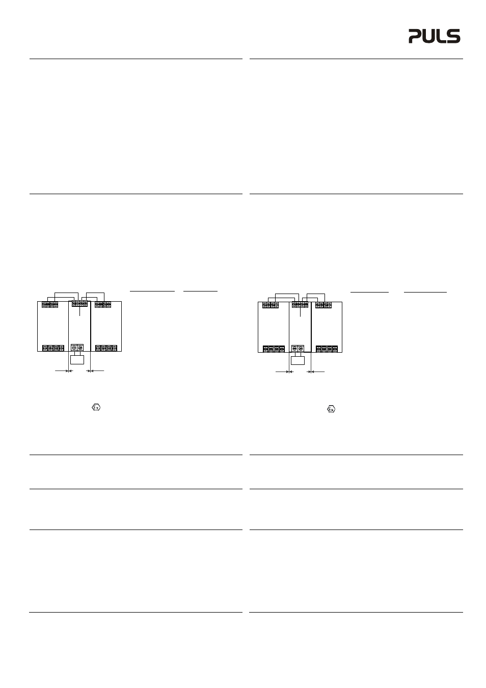
Keep the following installation clearances:
40mm on top, 20mm on the bottom,
5mm on the left and right sides are recommended when the redundancy module is loaded
permanently with more than 50% of the rated output current. Increase the side clearance to
15mm in case the adjacent device is a heat source (e.g. another power supply).
For 1+1 redundant applications, the clearance “A” can be reduced to 0mm in combination with
the following power supplies:
Redundancy Module Power
Supplies
YR2, YRM2
CD5, CS5, QS5, CS10,
CT10,
QS10
YR40.241 *)
QS20, CPS20, QT20
YR40.242 *)
QS20, CPS20
YR40.245 **)
QS40, XT40
YR40.482 *)
QS20, CPS20, QT20,
QS40,
QT40
YR80.241 **)
QS40, QT40, XT40
YR80.242 **)
QS40, XT40
*) Additional all unit with less or equal 10A nominal
output current.
**) Additional all unit with less or equal 20A nominal
output current.
Use in hazardous location areas
Units which are marked with "Class I Div 2" are suitable for use in Class I Division 2 Groups A, B,
C, D locations.
Units which are marked with
II 3G Ex nA nC IIC T4 Gc are suitable for use in Group II
Category 3 (Zone 2) environments and are evaluated according to EN 60079-0:2009 and EN
60079-15:2010.
WARNING EXPLOSION HAZARDS!
Substitution of components may impair suitability for this environment. Do not disconnect the unit
or operate the voltage adjustment unless power has been switched off or the area is known to be
non-hazardous. A suitable enclosure must be provided for the end product which has a minimum
protection of IP54 and fulfils the requirements of the EN 60079-15:2010.
Installation
Geeignet für DIN-Schienen gemäß EN 60715 oder EN 50022 mit einer Höhe von 7,5 oder 15mm.
Folgende Standard- Einbaulagen sind zu beachten:
YR2.DIODE, YRM2.DIODE, YR40.241:
Eingangsklemmen oben angeordnet
YR40.242, YR40.482, YR40.245, YR80.241, YR80.241: Eingangsklemmen unten angeordnet.
Für andere Einbaulagen siehe Datenblatt.
Das Gerät ist für Konvektionskühlung ausgelegt. Es ist für ungehinderte Luftzirkulation zu sorgen.
Luftzirkulation nicht behindern!
Folgende Einbauabstände sind einzuhalten:
Oben: 40mm, unten 20mm vom Gerät
Links und rechts sind 5mm empfohlen, wenn das Redundanzmodul dauerhaft mit mehr als
50% des Nennausgangsstroms belastet ist. Der Abstand muss auf 15mm erhöht werden,
wenn das benachbarte Gerät eine Wärmequelle ist (z.B. eine weitere Stromversorgung)
Der Abstand “A“ kann bei 1+1 Redundanzanwendungen auf 0mm reduziert werden, wenn
folgende Stromversorgungen verwendet werden:
Redundanzmodul Stromversorgungen
YR2, YRM2
CD5, CS5, QS5, CS10,
CT10,
QS10
YR40.241 *)
QS20, CPS20, QT20
YR40.242 *)
QS20, CPS20
YR40.245 **)
QS40, XT40
YR40.482 *)
QS20, CPS20, QT20
QS40,
QT40
YR80.241 **)
QS40, QT40, XT40
YR80.242 **)
QS40, XT40
*) Zusätzlich alle Geräte mit einem nominalen
Ausgangsstrom von 10A oder weniger.
**) Zusätzlich alle Geräte mit einem nominalen
Ausgangsstrom von 20A oder weniger.
Betrieb in explosionsgefährdeter Umgebung
Geräte, die mit "Class I Div 2" gekennzeichnet sind, sind für den Einsatz in Klasse I Division 2
Gruppen A,B,C,D Umgebung geeignet.
Geräte, welche die Kennzeichnung
II 3G Ex nA nC IIC T4 Gc tragen, sind nach EN 60079-
0:2009 und EN 60079-15:2010 getestet und können in einer Gruppe II, Kategorie 3 (Zone 2)
Umgebungen verwendet werden.
ACHTUNG EXPLOSIONSGEFAHR!
Veränderungen am Gerät können die Tauglichkeit für diese Umgebung beeinträchtigen.
Anschlüsse nicht abklemmen und Spannungseinstellung nicht verändern, solange Spannung
anliegt oder die Umgebung als explosionsgefährlich gilt. Das Gerät muss mindestens in ein IP54
Gehäuse, welches den Anforderungen der EN 60079-15:2010 entspricht, eingebaut werden.
CE Marking
CE mark is in conformance with EMC directive 2004/108/EC, the low-voltage directive (LVD)
2006/95/EC and the RoHS directive 2011/65/EU.
EMC Immunity: EN 61000-6-1, EN 61000-6-2
EMC Emission: EN 61000-6-3, EN 61000-6-4, FCC Part 15 Class B
CE Kennzeichnung
Das CE Zeichen ist angebracht und erklärt die Erfüllung der EMV Richtlinie 2004/108/EG, der
Niederspannungsrichtlinie 2006/95/EG und der RoHS Richtlinie 2011/65/EU.
Störfestigkeit: EN 61000-6-1, EN 61000-6-2
Störaussendung: EN 61000-6-3, EN 61000-6-4, FCC Part 15 Klasse B
Input Voltage Alarm Contacts
(only for YRM2.DIODE)
Both input voltages are monitored individually. If one input voltage is too low or completely
removed, it will be indicated by an alarm relay contact. The corresponding green LED on the front
of the unit will go off in this case.
Contact is closed when the input voltage is above 21.5V (±0.5V)
Contact ratings: max.: 60Vdc 0.3A, 30Vdc 1A, 30Vac 0.5A, resistive load, min. current 1mA
Eingangsspannungs-Alarmkontakte
(nur bei YRM2.DIODE)
Beide Eingangsspannungen werden getrennt überwacht. Fällt eine Eingangsspannung aus, wird
dieser Zustand mittels eines Relaiskontaktes gemeldet. Die zugehörige grüne LED an der
Vorderseite des Gerätes erlischt in diesem Fall.
Kontakt ist geschlossen sobald die Eingangsspannung größer als 21.5V (±0.5V) ist.
Kontakt Belastbarkeit: max.: 60Vdc 0.3A, 30Vdc 1A, 30Vac 0.5A, (R-Last), min. Strom 1mA
Dielectric Strength
The input and output voltages are floating and have no ohmic connection to ground.
Type and factory tests are conducted by the manufacturer. Field tests may be conducted in the
field using the appropriate test equipment which applies the voltage with a slow ramp (2s up and
2s down). Connect all input and output terminals together before the test is conducted.
When testing, set the cut-off current settings to the value in the table below.
Input or Output
Alarm Signals to
to Chassis
Input, Output or Chassis
Type Test (60s)
500Vac
500Vac
Factory Test (5s)
500Vac
500Vac
Field Test (5s)
500Vac
500Vac
Cut-off current setting
>2mA
>2mA
Isolationsfestigkeit
Die Eingangs- und Ausgangsspannung hat keine ohmsche Verbindung zur Erde oder zum
Schutzleiter. Typ- und Stückprüfungen werden beim Hersteller durchgeführt.
Wiederholungsprüfungen dürfen mittels geeigneten Prüfgenerators mit langsam (2s)
ansteigenden und abfallenden Spannungsrampen in der Anwendung erfolgen. Vor den Tests sind
alle Ein- und Ausgangspole miteinander zu verbinden. Während der Tests darf die Strom-
Abschaltschwelle nicht kleiner als der in der Liste angegebene Wert sein.
Eingang oder Ausgang
Alarm Signale zum Eingang,
zum Gehäuse
Ausgang oder Gehäuse
Typprüfung (60s)
500Vac
500Vac
Stückprüfung (5s)
500Vac
500Vac
Wiederholungsprüfung (5s)
500Vac
500Vac
Strom- Abschaltschwelle >2mA
>2mA
A
A
Load
+ +
- -
Power Supply 1
Output
Input
Redundancy
Module
Output
Input
1
Input
2
+
-
+
-
+
-
+ +
- -
Power Supply 2
Output
Input
A
A
Load
+ +
- -
Power Supply 1
Output
Input
Redundancy
Module
Output
Input
1
Input
2
+
-
+
-
+
-
+ +
- -
Power Supply 2
Output
Input