PULS UB10.241 User Manual
Page 4
DC UPS Instruction Manual
Bedienungsanleitung für DC USV der UB10-Serie
Terminals and Wiring
The units are equipped with spring-clamp terminals for the power port and with a plug connector
for the signal terminals. Use appropriate copper cables that are designed for an operating
temperatures of 60°C (for ambient up to 45°C) and 75°C (for ambient up to 60°C), minimum.
Follow national installation codes and regulations! Ensure that all strands of a stranded wire enter
the terminal connection! Ferrules are allowed, but not required.
Power Terminals
12V Output
Signals
Solid wire
0.5-6mm
2
0.1-2.5mm
2
0.2-1.5mm
2
Stranded wire
0.5-4mm
2
0.1-2.5mm
2
0.2-1.5mm
2
American wire gauge
20-10 AWG
28-12AWG
22-14 AWG
Wire stripping length
10mm / 0.4inch
8mm/0.33inch
6mm / 0.25inch
Tightening torque
N/A
0.4Nm/3.5lb.inch
0.4Nm/3.5lb.inch
Anschlussklemmen und Verdrahtung
Die Geräte sind mit Schnellanschluss-Federkraftklemmen ausgestattet. Verwenden Sie geeignete
Kupferkabel, die mindestens für 60°C (bei einer Umgebungstemperatur bis zu 45°C) und 75°C
(bei einer Umgebungstemperatur bis zu 60°C) zugelassen sind. Beachten Sie nationale
Bestimmungen und Installationsvorschriften! Stellen Sie sicher, dass keine einzelnen Drähte von
Litzen abstehen. Aderendhülsen sind erlaubt, aber nicht erforderlich.
Power Terminals
12V Output
Signals
Starrdraht 0.5-6mm
2
0.1-2.5mm
2
0.2-1.5mm
2
Litze 0.5-4mm
2
0.1-2.5mm
2
0.2-1.5mm
2
AWG
20-10 AWG
28-12AWG
22-14 AWG
Abisolierlänge
10mm / 0.4inch
8mm/0.33inch
6mm / 0.25inch
Anzugsdrehmoment nicht
anwendbar
0.4Nm/3.5lb.inch
0.4Nm/3.5lb.inch
Buffer time limiter (only at UB10.241/245)
The maximum buffer time during a buffer event can be limited to 10s, 30s, 1min, 3min or 10min
with this potentiometer. This saves the battery energy for faster recharge and expands the lifetime
of the battery. For longer buffer times choose ∞.
Buffer time limiter (nur bei UB10.241/245)
Mit diesem Einstellregler lässt sich die Pufferzeit auf 10s, 30s, 1Min, 3Min oder 10Min begrenzen,
um die Batterie zu schonen, und eine schnellere Nachladung zu erreichen. Für längere
Pufferzeiten wählen sie die Einstellung ∞.
End-of-charge-voltage or battery temperature selector
The end-of-charge-voltage can be set according to the expected temperature in which the battery
is located. For the UB10.241/245 the dial on the front of the unit allows a continuously adjustment
between +10 and +40°C. If in doubt about the expected temperature, set the unit to 35°C.
At the UB10.242 the expected battery temperature can be selected with 10°C, 20°C or 30°C.
Due to the additional internal temperature sensor of the UB10.242, a temperature compensated
battery charging is possible. For this option it can be selected if the battery temperature is as
same, 10°C or 20°C lower as the temperature of the DC UPS.
Ladeschlussspannung oder Batterie Temperatur Regler
Die Ladeschlussspannung kann mit diesem Regler in Abhängigkeit der zu erwartenden
Batterietemperatur eingestellt werden. Beim UB10.241/245 ist eine stufenlose Einstellung
zwischen +10°C und +40°C möglich. Im Zweifelsfall stellen Sie den Regler auf 35°C.
Beim UB10.242 können die Werte 10°C, 20°C oder 30°C eingestellt werden. Zusätzlich verfügt
das Gerät über einen internen Temperatursensor, der ein temperaturkompensiertes Laden der
Batterie erlaubt. Für diese Fälle kann beim UB10.242 zusätzlich eingestellt werden, ob die
Batterietemperatur identisch, 10°C oder 20°C niedriger als die Temperatur der DC-USV ist.
Signal relay contacts
Ready (1-2)
Contact is closed when battery is charged and the unit is ready to buffer.
Buffering (3-4)
Contact is closed when the unit is buffering.
Replace
battery (5-6) Contact is closed when the replacement of the battery is necessary.
Relay contact rating:
Max. 60Vdc 0.3A, 30Vdc 1A, 30Vac 0.5A resistive load; min. 1mA
at 5Vdc; 500Vac insulated to the power port.
Relais Kontakte
Ready (1-2)
Kontakt ist geschlossen, wenn die Batterie geladen und das Gerät
pufferbereit
ist
Buffering (3-4)
Kontakt ist geschlossen, wenn die DC-USV puffert
Replace
battery (5-6)
Kontakt ist geschlossen, wenn die Batterie ausgetauscht werden sollte.
Belastbarkeit
Max. 60Vdc 0.3A, 30Vdc 1A, 30Vac 0.5A Widerstandslast; min. 1mA
Relais Kontakte:
at 5Vdc; isoliert mit 500Vac gegenüber den Leistungsklemmen.
Inhibit Input
Buffering can be disabled or interrupted with the Inhibit input. The unit does not buffer (or stops
buffering) if in normal mode constant and in buffer mode for 250ms the voltage between 7 and 8 is
higher than 10V. Below 6V buffering is guaranteed possible.
The current of the inhibit input is limited to 6mA. The maximum voltage is 35Vdc. The isolation
voltage between the signal and the power port is 500Vac.
Inhibit Eingang
Mit dem „Inhibit“ Eingang kann eine Pufferung verhindert oder vorzeitig abgebrochen werden. Im
Normalbetrieb muss hierfür dauerhaft, im Pufferbetrieb für 250ms eine Spannung >10Vdc
zwischen den Klemmen 7-8 angelegt werden. Bei Spannungen kleiner 6V ist eine Pufferung
möglich. Der Signalstrom ist auf 6mA begrenzt, die maximale Spannung beträgt 35Vdc. Die
Isolationsspannung gegenüber den Leistungsklemmen beträgt 500Vac.
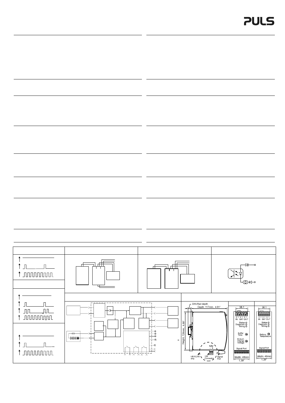
Green Status LED see Fig. 1
ON
When battery is charged, no wiring failure is recognized, input voltage is
sufficient and inhibit signal is not active.
1.25 Hz flashing
When battery is charging and the capacity is below 85%
10 Hz flashing
When the unit is in buffer mode
Grüne Status LED siehe Bild 1
AN
Wenn die Batterie vollständig geladen ist, kein Verdrahtungsfehler vorliegt; die
Eingangsspannung im spezifizierten Bereich liegt und der Inhibit nicht aktiv ist.
1,25 Hz blinkend
Wenn die Batterie geladen wird und weniger als 85% Kapazität aufweist.
10 Hz blinkend
Wenn die DC-USV im Pufferbetrieb ist.
Yellow Diagnosis LED see Fig. 2
ON
When
output
has switched off due to long overload in buffer mode or due to
high
temperature.
1.25 Hz flashing
When the battery failed the battery quality test (SoH test). Battery
should be replaced as soon as possible.
double flashing
When the output has switched off due to setting of the Buffer-timer Limiter. This
signal will be displayed for 15 minutes. (Not present at UB10.242)
5 Hz flashing
When buffering is disabled due to an active inhibit signal.
Gelbe Diagnose LED siehe Bild 2
AN
Wenn aufgrund von Überlast während des Pufferbetriebes der Ausgang
abgeschaltet wird oder bei Übertemperatur.
1,25 Hz blinkend
Wenn die Batterie den Qualitätstest nicht besteht. Batterie sollte
baldmöglichst ersetzt werden.
zweifach blinkend
Wenn der Ausgang, aufgrund einer abgelaufenen Pufferzeit abgeschaltet
wurde.
Die Meldung wird 15 Minuten lang angezeigt. (Nicht bei UB10.242)
5 Hz blinkend
Wenn ein aktives Inhibit Signal die Pufferung verhindert.
Red Check Wiring LED
ON
When a failure in the wiring, battery, battery fuse or installation exists (e.g. too low
or to high input voltage).
Rote Check Wiring LED
AN
wenn eine Überprüfung der Batterie, der Verdrahtung zwischen DC-USV und Batterie
oder bei zu kleiner oder zu hoher Eingangsspannung.
Fig. 1/ Bild 1
Green Status / Grüne Status LED
Fig. 3 / Bild 3
Wiring / Verdrahtung UB10.245
Fig. 4 / Bild 4
Wiring / Verdrahtung UB10.241/242
Fig. 5 / Bild 5
Inhibit Input / Inhibit Eingang
Ready
Charging
Buffering
ON
OFF
ON
OFF
ON
OFF
Fig. 2 / Bild 2
Yellow Diagnosis / Gelbe Diagnose LED
24V
Power
supply
+
-
N
L PE
24V
buffered
branch
DC-UPS
UB10.245
24V
IN
24V
OUT
12V
BAT
+
-
+
-
+
-
12V
Battery
+
-
+
-
12V
12V
buffered
branch
+
-
+
-
24V
Power
supply
+
-
N
L PE
24V
buffered
branch
DC-UPS
UB10.245
24V
IN
24V
OUT
12V
BAT
+
-
+
-
+
-
12V
Battery
+
-
+
-
5,1V
3mA
+
- 7
8
Fig. 6 / Bild 6
Functional Diagram / Funktionsschaltbild
Fig 7 / Bild 7
Dimension / Abmessung
UB10.241/245 UB10.242
Overload
Replace
Battery
Buffer time
expired
Inhibit
active
ON
OFF
ON
OFF
ON
OFF
ON
OFF
UB10.241/245
Overload
Replace
Battery
Inhibit
active
ON
OFF
ON
OFF
ON
OFF
UB10.242
Battery
Charger
24V
Power Supply
Input
-
+
Reverse
Polarity
Protection
Input Fuse
&
*
Electronic
Current
Limiter
Buffered
Load
+
-
24V Output
Step-up
Converter
Step-down
Converter
+
-
(5)
(6)
Controller
Diagnosis LED (yellow)
Check Wiring LED (red)
Status LED (green)
Buffer-time Limiter
10s, 30s, 1m, 3m, 10m,
(only UB10.241/245)
End-of-charge Voltage
Battery Temperature
Inhibit -
Inhibit +
Replace Battery
Contact
(7)
(8)
12V Output
(UB10.245 only)
Buffered
Load
-
12V Battery
Battery
Tester
Cut-off
Relay
Battery
+
-
+
Ready
Contact
(1)
(2)
Buffering
Contact
(3)
(4)
PU-357.012.00-10B