PULS QS20.241-A1 User Manual
Page 4
QS20 Power Supply Instruction Manual
QS20 Bedienungsanleitung für Stromversorgung
Input Fuses
Internal input fuse included, not user accessible. The unit is tested and approved for branch
circuits up to 20A. An external protection is only required if the supplying branch has an ampacity
greater than this, however, in some countries local regulations might apply. Check also local
codes and requirements. If an external fuse is necessary or utilized, minimum requirements need
to be considered to avoid nuisance tripping of the circuit breaker. A minimum value of 10A B- or
6A C-Characteristic breaker should be used. (QS20.244: 10A B- or C-Characteristic)
Sicherungen am Eingang
Das Gerät besitzt eine eingebaute Eingangssicherung, die nicht anwenderzugänglich ist. Das
Gerät ist geprüft und zugelassen zum Anschluss an Stromkreisen bis max. 20A. Ein zusätzlicher
externer Schutz ist nur erforderlich, wenn der Speisestromkreis mit einem höheren Wert
abgesichert ist oder nationale Richtlinien es vorschreiben. Falls ein externes Schutzelement
verwendet wird, soll dieses nicht kleiner als 10A B- oder 6A C-Charakteristik sein, um ein
fehlerhaftes Auslösen zu vermeiden. (QS20.244: 10A B- oder C-Charakteristik)
Terminals and Wiring
Use appropriate copper cables that are designed for a minimum operating temperature of:
60°C for ambient temperatures up to 45°C,
75°C for ambient temperatures up to 60°C and
90°C for ambient temperatures up to 70°C.
Follow national installation codes and regulations! Ensure that all strands of a stranded wire
enter the terminal connection! Ferrules are allowed.
Input and Output
DC-OK Signal
Solid wire
0.5-6mm
2
0.3-4mm
2
Stranded wire
0.5-4mm
2
0.3-2.5mm
2
American wire gauge
20-10 AWG
26-12 AWG
Wire stripping length
7mm / 0.28inch
6mm / 0.25inch
Anschlussklemmen und Verdrahtung
Verwenden Sie geeignete Kupferkabel, die mindestens für:
60°C bei einer Umgebungstemperatur bis zu 45°C,
75°C bei einer Umgebungstemperatur bis zu 60°C und
90°C bei einer Umgebungstemperatur bis zu 70°C zugelassen sind.
Beachten Sie nationale Bestimmungen und Installationsvorschriften! Stellen Sie sicher, dass
keine einzelnen Drähte von Litzen abstehen. Aderendhülsen sind erlaubt.
Eingang und Ausgang
DC-OK Signal
Starrdraht 0.5-6mm
2
0,3-4mm
2
Litze 0.5-4mm
2
0,3 -2,5mm
2
AWG
20-10 AWG
26-12 AWG
Abisolierlänge
7mm / 0,28inch
6mm / 0,25inch
Indicators and Relay Contacts
Overload LED
DC-OK LED
DC-OK Contact
Normal mode
OFF
ON
Closed
During BonusPower
®
OFF
ON
Closed
Overload (Vout < 90%)
*)
OFF
Open
Output short circuit
*)
OFF
Open
Temperature Shut-down
*)
OFF
Open
No input power
OFF
OFF
Open
*) The overload LED is permanently on when the overload current is continuously flowing. During
the 17s rest period (hiccup), the red LED is flashing with a frequency of approx. 1.3Hz.
Anzeigelampen und Relaiskontakt
Overload LED
DC-OK LED
DC-OK Kontakt
Normalberieb AUS
EIN
geschlossen
Während BonusPower
®
AUS
EIN
geschlossen
Überlast (Vout < 90%)
*)
AUS
offen
Ausgangskurzschluss *) AUS
offen
Temperaturabschaltung *)
AUS
offen
Keine Eingangsspannung
AUS
AUS
offen
*) Die „Overload LED“ leuchtet dauernd, wenn der Überlaststrom kontinuierlich fließt. Während
der 17s Auszeit im Hiccup Modus blinkt die LED mit einer Frequenz von ca. 1,3Hz.
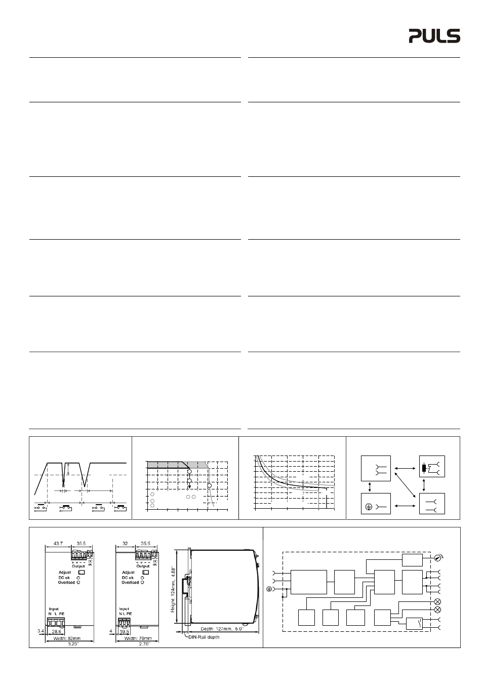
DC-OK Relay Contact
(see Fig. 1)
This feature monitors the output voltage, which is produced by the power supply, and is
independent of a return voltage from a unit which is connected in parallel.
Contact closes when the output voltage reaches the adjusted value after turn-on of the power
supply or when the output voltage reaches 90% after a dip of the output.
Contact opens when the output voltage dips more than 10%. Short dips will be extended to a
length of 250ms. Dips shorter than 1ms will be ignored.
Contact ratings: max.: 60Vdc 0.3A, 30Vdc 1A, 30Vac 0.5A, Resistive load, min.: 1mA
DC-OK Relais Kontakt
(siehe Bild 1)
Diese Funktion überwacht die vom Gerät erzeugte Ausgangsspannung und lässt sich von einer
rückwärts eingespeisten Spannung nicht beeinflussen (z.B.: bei Parallelschaltung)
Kontakt schließt sobald nach dem Einschalten der Ausgang den eingestellten Wert erreicht
oder wenn nach einem Einbruch des Ausgangs die Spannung wieder > 90% des eingestellten
Wertes wird.
Kontakt öffnet sobald der Ausgang um mehr als 10% einbricht. Kurze Einbrüche werden auf
250ms verlängert. Einbrüche kürzer 1ms werden ignoriert.
Belastbarkeit: max.: 60Vdc 0.3A, 30Vdc 1A, 30Vac 0.5A, (R-Last), min.: 1mA
Overload and Hiccup
PLUS
Characteristic
(see Fig. 2 and 3)
The units are no-load, overload and short-circuit proof. The units are designed to support loads
with a continuous power demand of up to 480W and a short-term (see Fig. 3) power demand of
up to 720W without damage or shut-down.
If the power requirement is continuously higher than 480W and the voltage falls below approx.
85% of its nominal value (due to the current regulating mode at overload), the unit shuts-off and
makes periodical restart attempts (Hiccup
PLUS
mode). In such cases, the unit will be off for 17s
followed by an on cycle of 4s max. 720W. This cycle is repeated as long as the overload exists.
Überlastverhalten und Hiccup
PLUS
Modus
(siehe Bilder 2 und 3)
Die Stromversorgung ist zur Versorgung von Lasten mit kurzzeitig hohem Bedarf an
Spitzenleistung und kann für eine bestimmte Zeit (Bonuszeit) bis zu 720W Ausgangsleistung
liefern, bevor automatisch auf 480W zurückgeregelt wird. Wenn der Leistungsbedarf
kontinuierlich höher als 480W ist und durch die Stromregelkennline der Stromversorgung die
Ausgangsspannung unter ca. 85% fällt, schaltet die Stromversorgung ab und macht periodische
Startversuche (Hiccup
PLUS
-mode). In solchen Fällen schaltet die Stromversorgung für 17s aus
und macht dann einen neuen Startversuch, bei dem wieder für 4s die 720W zur Verfügung
stehen. Der Vorgang wiederholt sich solange die Überlast besteht.
Dielectric Strength
(see Fig. 4)
The output voltage is floating and separated from the input according to SELV (IEC/EN 60950-1)
and PELV (EN 60204-1, EN 50178; IEC 62103, IEC 60364-4-41) requirements. Type and factory
tests are conducted by the manufacturer. Field tests may be conducted in the field using the
appropriate test equipment which applies the voltage with a slow ramp (2s up and 2s down).
Connect all phase-terminals together as well as all output poles before the test is conducted.
A B C D
Type Test
(60s)
2500Vac
3000Vac
500Vac
500Vac
Factory Test
(5s)
2500Vac
2500Vac
500Vac
500Vac
Field Test
(5s)
2000Vac
2000Vac
500Vac
500Vac
Cut-off current setting
>15mA
>15mA
>40mA
>1mA
Isolationsfestigkeit
(siehe Bild 4)
Die Ausgangsspannung hat keinen Bezug zur Erde oder Schutzleiter und ist zum Eingang nach
den SELV (IEC/EN 60950-1) und PELV (EN 60204-1, EN 50178, IEC 62103, IEC 60364-4-41)
Standards getrennt. Typ- und Stückprüfungen werden beim Hersteller durchgeführt.
Wiederholungsprüfungen dürfen mittels geeigneten Prüfgenerators mit langsam (2s)
ansteigenden und abfallenden Spannungsrampen in der Anwendung erfolgen. Vor den Tests
sind alle Phasen wie auch alle Ausgangspole miteinander zu verbinden.
A
B
C
D
Typprüfung
(60s) 2500Vac 3000Vac 500Vac 500Vac
Stückprüfung
(5s) 2500Vac 2500Vac 500Vac 500Vac
Wiederholungsprüfung (5s) 2000Vac 2000Vac 500Vac 500Vac
Strom-
Abschaltschwelle
>15mA >15mA >40mA >1mA
Fig. 1 / Bild 1
DC-OK-Signal / DC-OK-Signal
Fig. 2 / Bild 2
Output Characteristic (typ.) / Ausgangskennlinie
Fig. 3 / Bild 3
BonusPower
®
Time / BonusPower
®
Zeit
Fig. 4 / Bild 4
Isolation / Isolation
250ms
90% V
ADJ
<1ms
10%
open
V
OUT
= V
ADJ
open
closed
closed
>1ms
Output Voltage
0
0
5
10
20
25
4
8
12
28V
16
20
24
40A
15
30
Output
Current
35
A
B
A
B
Short term <5s then auto
switching to curve +
Below 20Vdc hiccup mode
C
C
Continuously available
B
C
0
528W
576W
624W
672W
720W
768W
1
2
3
7
4
5
6
8
9
10s
Output Power
min
max
typ
A
D
C
B
B
Input
DC-ok
Earth
Output
-
+
N
L
Fig. 5 / Bild 5 Dimensions / Abmessungen
all units except QS20.244
QS20.244
all units
Fig. 6 / Bild 6
Functional Diagram / Funktionsschaltbild
+
+
-
-
Output
Over-
Voltage
Protection
PFC
Converter
Output
Voltage
Regulator
Power
Converter
Output
Filter
DC-ok
Relay
Output
Voltage
Monitor
Output
Power
Manager
Temper-
ature
Shut-
down
Input Fuse
Input Filter
Input Rectifier
Active Inrush Limiter
V
OUT
L
N
DC-ok
Contact
Overload
LED
DC-ok
LED
*) except / außer QS20.244
*)
PU-362.013.00-10B