Sterling QVSB User Manual
Page 4
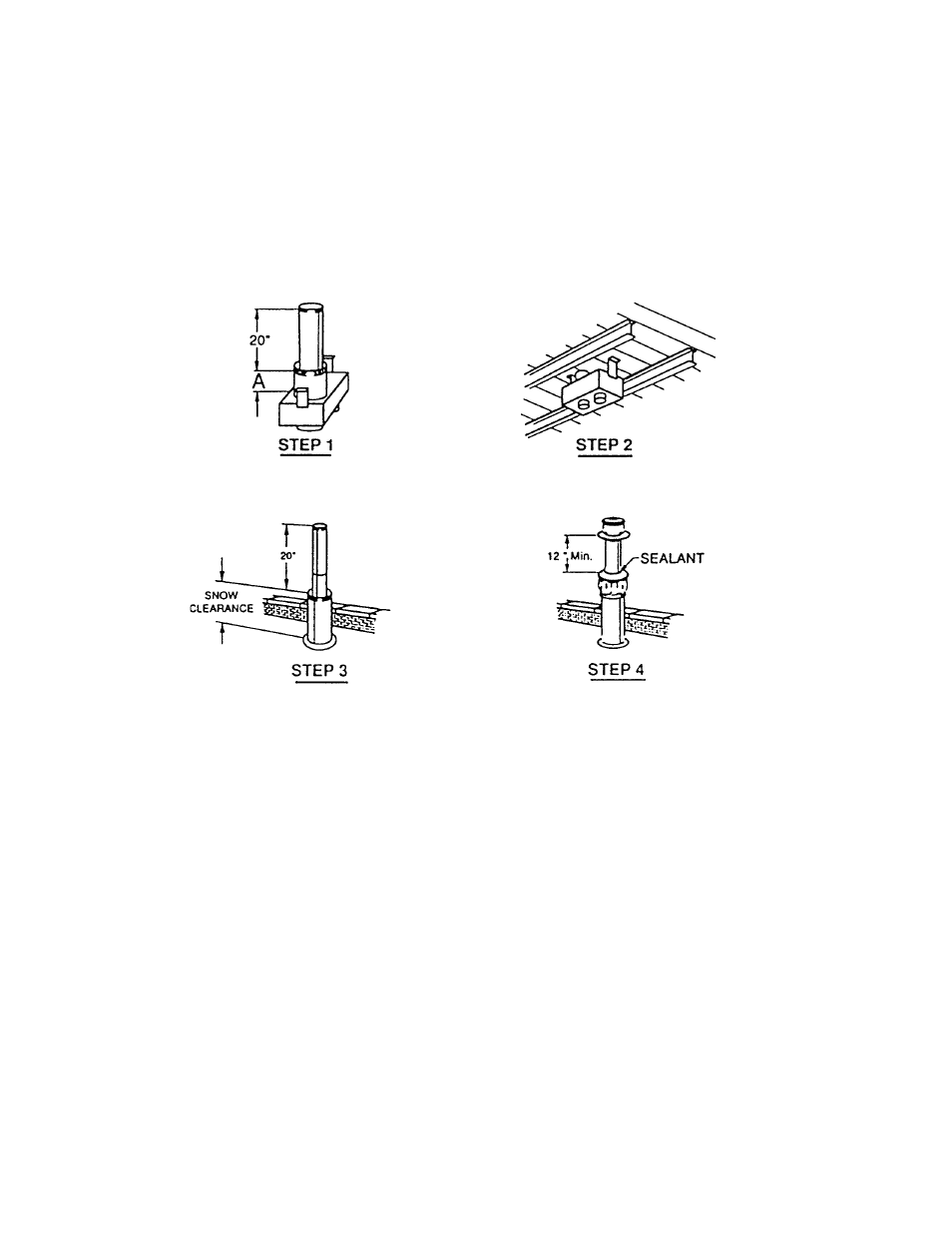
Insert pipe through roof and fasten adapter box in place. See fi gure 4, step 2.
Flash and/or caulk 8 inch pipe to roof. See fi gure 4, step 3.
Install inlet air cap on 8 inch pipe and fasten with sheet metal screws. Install fl ue terminal on 5
inch pipe and fasten in place. Seal joint between 5 inch pipe and inlet air cap with silicone
sealant to prevent entry of water. See fi gure 4, step 4.
Figure 4
Connect fl ue pipe and combustion air pipe from concentric adapter to unit. Pipe must be single
wall 26 gauge or heavier galvanized steel or a material of equivalent durability and corrosion
resistance. Pipe diameter must be as listed under “INLET & FLUE SIZE” in Table 1 on page 1of
Installation Instructions BSCII or PSCII or SCDFM. The equivalent length of the exhaust vent pipe
must be a minimum of 5 feet and a maximum of 50 feet. For propeller units, the equivalent length equals
the total length of straight pipe plus 10 feet for each 90 degree elbow and 5 feet for each 45 degree
elbow. For duct furnaces and blower units, the equivalent length equals the total length of straight pipe
plus 15 feet for each 90 degree elbow and 5 feet for each 45 degree elbow. Secure each joint with a
minimum of 3 corrosion resistant screws. Seal all joints of the exhaust vent pipe with two full turns of
3M #425 Aluminum Foil Tape or its equivalent suitable for 550 degrees F. or high temperature silicone
sealant. Seal all joints of the combustion air inlet pipe with two full turns of duct tape or aluminum
foil tape or silicone sealant. Do not enclose the exhaust vent pipe or run the pipe within 6 inches of
combustible material.
4