Horizontal concentric vent kit (option #m5), Top view, Rear view – Sterling SVF User Manual
Page 2
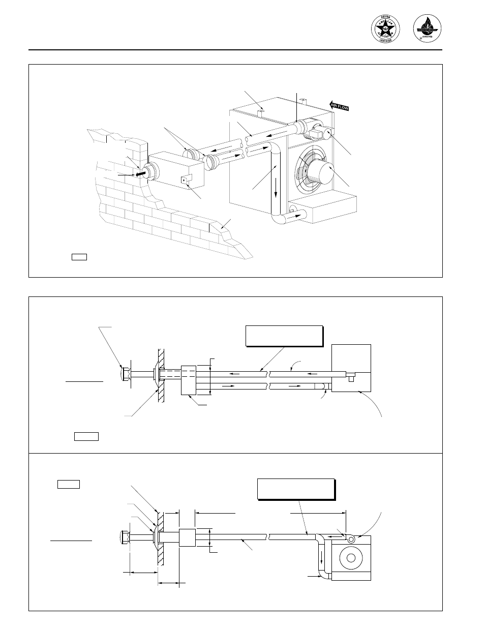
Figure 2– Typical Horizontal Vent Kit Installation
Figure 3– Typical Horizontal Vent Kit Installation Requirements
HORIZONTAL CONCENTRIC VENT KIT (Option #M5)
Separated Combustion Unit
Flue Discharge
Combustion
Air Inlet
Fan/Motor Assembly
Power Venter Assembly
Increasers As Required
(Field Supplied)
Wall
D4500
Reducer/increaser As Required
(Reducer Is Field Supplied)
Terminate To Vertical
Requirements Shown In
Figure 3.
To Outside Vent Cap
(2) Mounting Brackets
(Field Supplied)
Flue Terminal Assembly
(Field) Part # 3605 (Shown)
or (Breidert) Part # 2221-2
17 In. (432)
Concentric Vent Box
Part # 3603
Wall
Size Pipes According To
Table 1.
Flue
Discharge
Combustion
Air Inlet
Top View
Separated
Combustion
Unit
D4498-1
7 In.
(178)
10 In.
(254)
Thimble
Inlet Air Screen
Part# 3604
Size Pipes According To
Table 1.
6 Ft. (1.8 m) Min.
30 Ft. (9.2 m) Max.
60 In. (1524) Max.
Rear View
Pitch Pipes To Drain
1/4" Per Foot
Combustion
Air Inlet
Flue
Discharge
D4498-2
Separated
Combustion
Unit
16 In. (406) Min.
24 In. (610) Max.
Wall