Figure 23 figure 24 – Sterling GG User Manual
Page 36
36
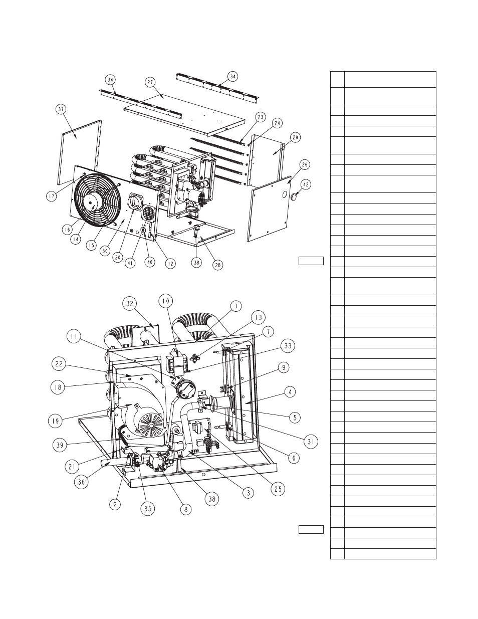
IDENTIFICATION OF PARTS
TUBULAR 30-120 MBH UNIT SIZES
1
Vestible Panel/Tube Assembly
(Heat
Exchanger)
2 Bracket/Gas
Train
3 Manifold
4 Burner
Assembly
5
*Standard
Orifi
ce
Natural Gas or Propane (LP) Gas
6 Spark
Ignitor
7 Flame
Sensor
8
Gas
Valve
Natural or Propane (LP) Gas
9
Manual Rollout Safety Switch
10
Transformer, 50 VA, 115/24
11
Air Pressure Switch
12
Terminal Block Plate
13
High Limit Switch
14 Fan Motor
15
OSHA Fan Guard
16 Standard Fan
17
Fan/Guard/Motor
Mount
Hardware
Kit
18 **Flue Collector
19
Power Venter (Drafter) Assembly
20
Flue Collar Assembly
21
Vinyl Tubing (Pressure Switch)
22
Power Venter Mounting Plate
23 Louver
24 Louver Spring
25 Control Board
26 Access Panel
27
Top Jacket Panel w/Insulation
28
Bottom Jacket Panel w/Insulation
29
Front Jacket Panel
30
Rear Jacket Panel
31 Bracket, Manifold
32
Tube Support Bracket
33
Green Ground Screw
34 Hanger Bracket
35 Manifold Clamp
36 Pipe Nipple
37
Left Side Panel
38
Manifold Support Bracket Kit
39 Spring
40 Grommet
41
Inlet Screen Assembly
42
Burner Box View Port
Item
No.
ItemDescription
**
* The orifi ce shown are for units operating
at normal altitudes of 0 to 2000 feet
(610m).
*
** When replacing a fl ue collector, make
sure that the fl ue collector box is sealed
completely with factory supplied gasket.
Figure 23
Figure 24
D8600
D6931B