Diagram 3, Diagram 4, Diagram 5 – Athena Technologies C.5 EU User Manual
Page 30: Diagram 6, Diagram 7, S.5 connection, C.5 connection, Placement, C.5 placement
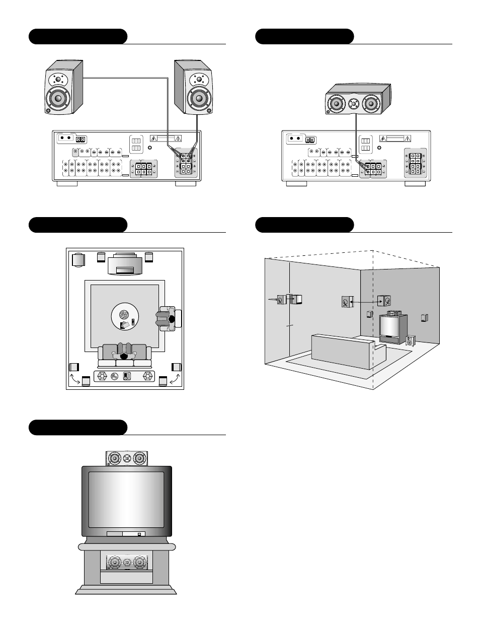
S.5 Connection
DIAGRAM 3
Sub woofer
out
Rear out
Monitor
out
VCR 1
VCR 2
Phono
CD
Tape 1
Tape 2
VCR 1
VCR 2
Left
Right
Audio
Video
Out In
(rec) (Play)
Out In
(rec) (Play)
Out In
(rec) (Play)
Out In
(rec) (Play)
AC Outlets
Antenna
Front
Speaker
Center
Speaker
Rear
Speakers
Left
Right
C.5 Connection
DIAGRAM 4
Rear out
Monitor
out
VCR 1
VCR 2
Phono
CD
Tape 1
Tape 2
VCR 1
VCR 2
Left
Right
Audio
Video
Out In
(rec) (Play)
Out In
(rec) (Play)
Out In
(rec) (Play)
Out In
(rec) (Play)
AC Outlets
Antenna
Front
Speaker
Center
Speaker
Rear
Speakers
Left
Right
R
L
Placement
DIAGRAM 5
Placement
DIAGRAM 6
2/3
1/3
C.5 Placement
DIAGRAM 7