Pfister 8N8-CT0C User Manual
Page 5
6 HANDLE ATTACHMENT (Fig.C)
Place Handle Hub (1) on Valve Stem (3) and secure with
Set Screw (2) (do not over tighten). To remove handle
reverse steps.
7 VALVE FUNCTION (Fig.D)
By lifting the Lever Handle (1) up, the valve will be acti-
vated allowing water to flow. The water flow will increase
by continuing to lift up the Lever Handle (1). By rotating the
Lever Handle counter-clockwise, the water temperature will
decrease to cold flow only. By rotating the Lever Handle
clockwise, the water temperature will increased to hot flow
only.
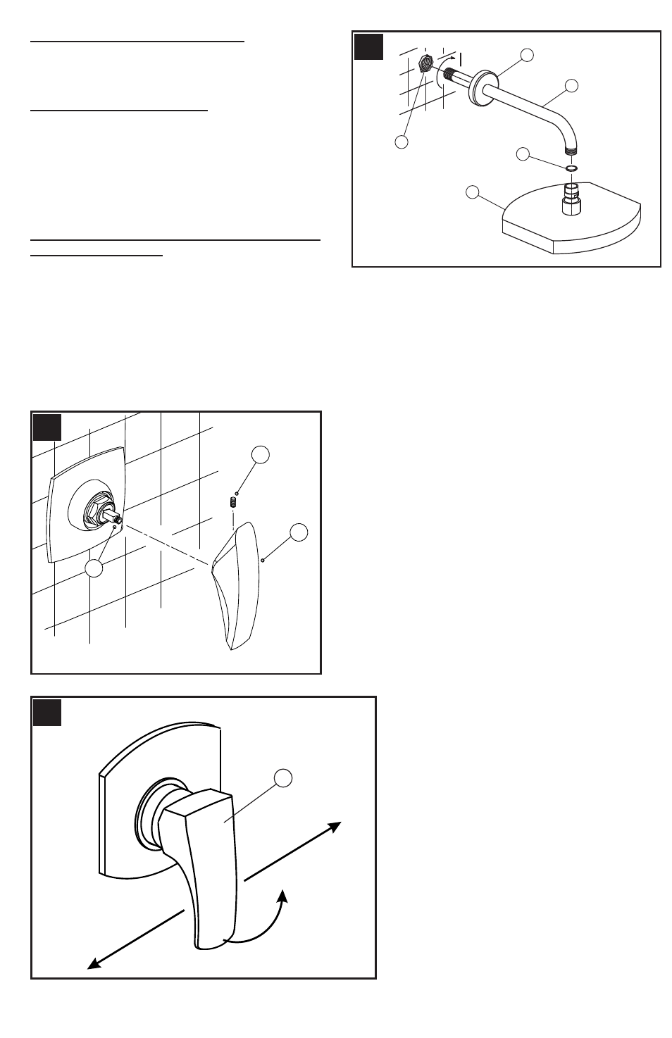
8 SHOWER ARM AND SHOWER HEAD IN-
STALLATION (Fig.E)
For shower only products: Insert the end of Shower Arm
(1) through the Shower Flange (2). Apply PTFE plumber's
tape to both ends of Shower Arm (1) according to manufac-
turer's instructions. Screw the long end of Shower Arm (1)
into pipe (3) elbow inside the wall. Slide Shower Flange (2)
tight to the wall. Screw the shower head (4) to the Shower
Arm (1), placing the Washer (5) in between.
E
5
2
1
4
3
1
3
2
C
HOT
OPEN
COLD
1
D
5