Val-Matic Wafer and Globe Style Silent Check Valve User Manual
Page 6
TROUBLESHOOTING
Several problems and solutions are presented below
to assist you in trouble shooting the valve assembly
in an efficient manner.
• Valve Chatters or Vibrates: Verify that velocity is
at least 4 feet per second. Noise sounding like
rocks in the line can be cavitation due to high
velocities, low downstream pressure, or an
upstream expanded. Verify that there are three
diameters of straight pipe upstream.
• Valve Leakage: Check upstream gasket and
flange to verify that inside diameter meets the
maximum “A” dimension given in Drawing SS-974.
face,
then mating flange and gasket are not securing
the seat properly.
5
WARNING: The line must be drained before
removing the valve or pressure
may be released causing injury.
Drain line, remove valve, and inspect seating
surfaces. If seat (2) is lifted above flange
• Valve Does Not Pass Flow: Check flow arrow
direction on valve body. Verify that downstream
isolation valve is open and there is no line
blockage downstream.
• Valve Slams: Remove valve and inspect spring.
Heavier springs can be furnished for severe high-
head applications. Consult factory if the valve is
installed in a vertical pipe with the flow downward.
flow
support for th
2x4 board across the seat (2) and secure with C-
clamps to th
flange. For the globe style
valve, remove the seat retaining screws (6) and
seat (2). For the wafer style valve and 2-1/2”
globe style valve, unthread the seat (2) from the
body (2) in a counterclockwise direction.
2. For the globe style valves, examine narrow flange
on the outside diameter of the seat (2). The
retaining screws should have left a shallow dimple.
If a deep depression is present, the gasket and
flange internal diameters should be checked to
verify that they are greater than “A” on drawing
SS-974.
3. Flip the seat (2) over and inspect the seating
surface. Some minor dents and discoloration are
normal. Grooves or wear areas will cause leakage
and requires seat replacement. Note: Replace
seat if the optional resilient seat o-ring is worn or
damaged.
4. Lift disc (3) from body. Inspect shafts and seating
surfaces for wear. The shaft diameter is normally
about 1/32” smaller in diameter than the hole in
the seat (2) and bushing (5). Some minor dents
and discoloration are normal. Wear areas will
cause leakage and require seat replacement.
Heavy mineral deposits should be removed with
lapping compound or fine sand paper.
5. Remove spring (4) and check for wear or cracks.
6. Remove bushing (5) and inspect for wear. The
inside diameter of the bushing should be about
1/32” larger in diameter than the shaft.
SE
m
es should
e
ire b
tion of
e
hine
parts,
a
als should
during
a
.
r
. In
aining screws (6). 12”
an
y require a 2x4 board and C-
clamps to compress the spring into the body. For
the
the
follo
DISASSEMBLY
The valve should be removed from the pipeline for
disassembly. A skilled mechanic with proper tools
should perform all work on the valve. Refer to
Figure 2 or 3.
1. Lay valve on flat surface or bench with the
arrow facing down. 12” and larger valves require
e spring during disassembly. Place a
e valve
REAS
MBLY
ll parts
ust be clean and gasket surfac
A
b
cleaned with a stiff w
rush in the direc
serrations r mac
marks. Worn
th
o
skets, and e
be replaced
g
s
ssembly.
re
1 Insert bushing (5 into body (1). The bushing is
)
e ined by the pring.
ta
s
2. Lay spring (4) and disc (3) over bushing (5).
3
stall seat (2) with the ret
d larger valves ma
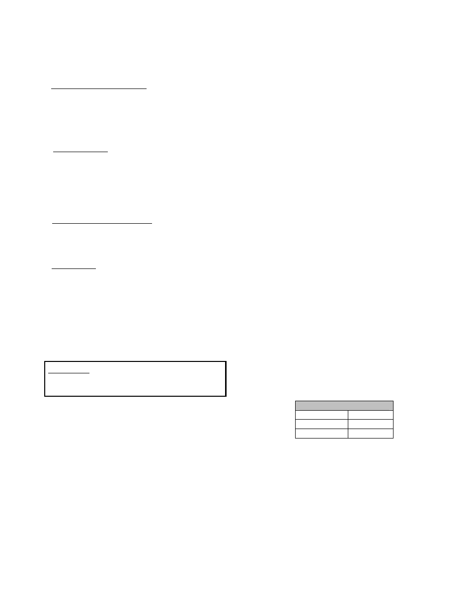
thread seat valves, tighten the seats to
wing values:
Threaded Seat Torque
Valve Size
Torque
2”-3” 25
ft-lbs
4”-10” 50
ft-lbs
4. Install new gaskets and valve. Tighten flange
bolts evenly using the crossover tightening method
and the torque values given in Table 1 on page 2.