Installation – Val-Matic 2-12 in. (DN 50-300 mm) Wafer Style Dual Disc Check Valve User Manual
Page 3
INSTALLATION
The installation of the valve is important for its
proper operation. The flow arrow on the valve body
must point in the direction of flow when the system is
in operation. The valve can be installed in horizontal
lines with the disc hinge pin in the vertical position,
or in vertical lines with the flow up. Valves for air
service (Series 8900) require special springs to allow
full valve opening.
CAUTION: When installed in horizontal lines,
the check valve must be installed
with the disc hinge pin in the
vertical position
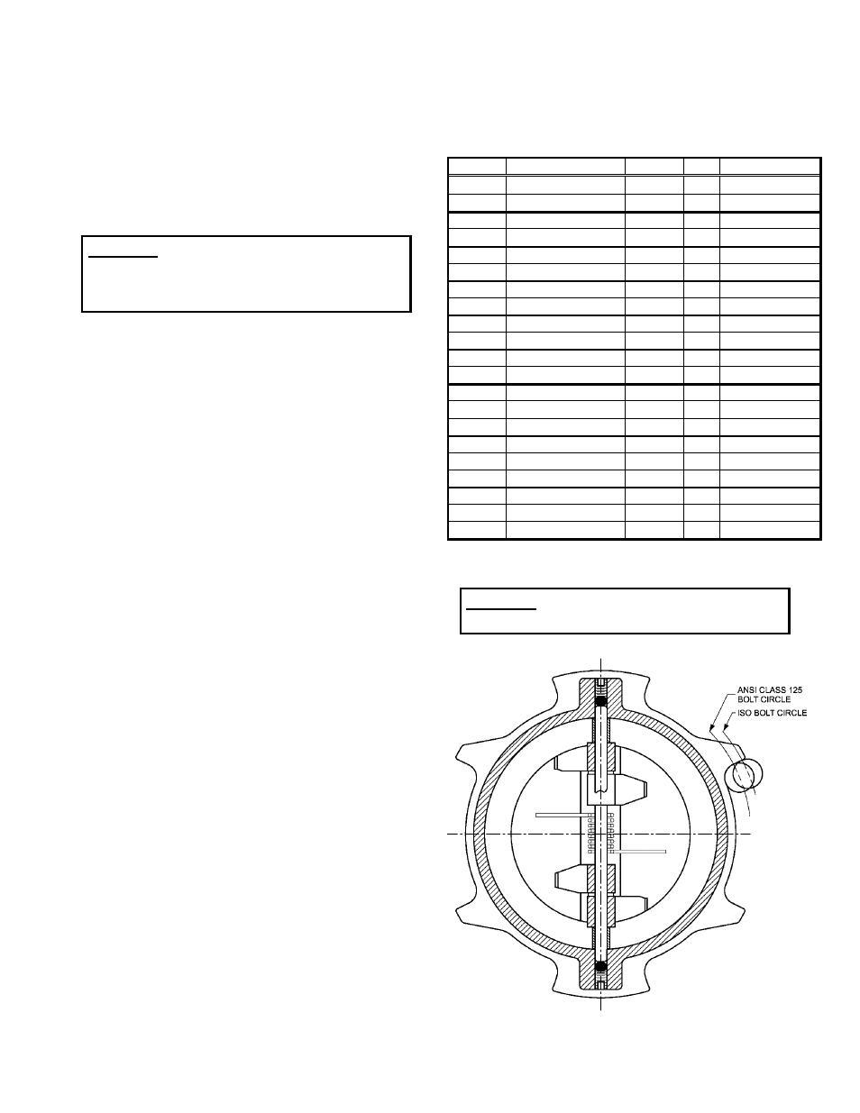
The valve should be installed between standard
flanges that correspond to the dimensions given in
ANSI B16.1 for 125# flanges or to those given in
ISO 7005 for PN10 and PN16 flanges (See Table 1).
Special integrally-cast locating tabs are provided
around the exterior to enable the valves to fit
between these different bolt patterns. (See Figure 2)
The number of tabs varies by valve size. (Note: for
some sizes tabs are not provided because the
desired universal fit is accomplished without them)
The gasket can be rubber or compressed fiber.
Ring gaskets are appropriate for this wafer style
check valve, but full-face flange gaskets may be
substituted. The studs or bolts used should span
the full length of the valve.
Three diameters of straight pipe upstream of the
valve are recommended to prevent turbulent flow
streams through the valve, which can cause
vibration and wear.
When mating the check valve with butterfly isolation
valves, the isolation valve must be installed at least
one diameter downstream of the check valve,
because, in most sizes, the check valve discs
extend beyond the downstream flange face and may
interfere with the operation of adjacent valves. In
these sizes, a short run of pipe or spacer is needed
between the check valve and the isolation valve.
INSTALLATION PROCEDURE: Lower valve
between mating flanges. NPS 10-12 (DN 250-300)
valves are provided with a lifting eyebolt to aid in this
process. Lubricate the flange bolts or studs and
insert them around the flange. Lightly turn bolts or
nuts until gaps are eliminated. The tightening of the
nuts should then be done in graduated steps using
the cross-over tightening method. Recommended
lubricated torques for use with resilient gaskets are
given in Table 1.
If leakage occurs, allow gaskets to absorb fluid and
check torque and leakage after 24 hours. Do not
exceed bolt rating or crush gasket more than 50 per
cent of its thickness.
Size
Class
Bolt size Qty
Bolt Torque
NPS 2
ANSI 125#
5/8 in.
4
25-75 ft-lb
DN 50
ISO 7005 PN16
M16
4
40-120 N-m
NPS 2.5
ANSI B16.1 125#
5/8 in.
4
25-75 ft-lb
DN 65
ISO 7005 PN16
M16
4
40-120 N-m
NPS 3
ANSI B16.1 125#
5/8 in.
4
25-75 ft-lb
DN 80
ISO 7005 PN16
M16
8
40-120 N-m
NPS 4
ANSI B16.1 125#
5/8 in.
8
25-75 ft-lb
DN 100
ISO 7005 PN16
M16
8
40-120 N-m
NPS 5
ANSI B16.1 125#
3/4 in.
8
40-120 ft-lb
DN 125
ISO 7005 PN16
M16
8
40-120 N-m
NPS 6
ANSI B16.1 125#
3/4 in.
8
40-120 ft-lb
DN 150
ISO 7005 PN16
M20
8
65-200 N-m
NPS 8
ANSI B16.1 125#
3/4 in.
8
50-150 ft-lb
DN 200
ISO 7005 PN10
M20
8
65-200 N-m
DN 200
ISO 7005 PN16
M20
12
65-200 N-m
NPS 10
ANSI B16.1 125#
7/8 in.
12
60-180 ft-lb
DN 250
ISO 7005 PN10
M20
12
65-200 N-m
DN 250
ISO 7005 PN16
M24
12
100-300 N-m
NPS 12
ANSI B16.1 125#
7/8 in.
12
65-200 ft-lb
DN 300
ISO 7005 PN10
M20
12
80-240 N-m
DN 300
ISO 7005 PN16
M24
12
125-375 N-m
TABLE 1. FLANGE BOLT TORQUES
CAUTION:
The use of excessive bolt torque
may damage valve.
FIGURE 2. INTEGRALLY-CAST LOCATING TABS
2