Val-Matic Rubber-Seated Ball Valve User Manual
Page 11
11
REASSEMBLY
All parts must be cleaned and gasket surfaces should
be cleaned with a stiff wire brush in the direction of the
serrations or machine marks. Worn parts, gaskets and
seals should be replaced during reassembly. Valve
and actuator mounting bolts should be lubricated and
torqued per Table 7 during reassembly.
TABLE 7. LUBRICATED BOLT TORQUES
1. Place the long body half (1A) on the floor or
bench. Insert the grit seals (10) in the bores.
2. Apply a bead of loctite 680 on new sleeve
bearings (5) and insert into both ends of the valve
body (1A) until flush with grit seal. Insert the
shafts (4) through the body and grit seals (10).
3. Lower the ball (3) into place with a nylon strap and
lower the taper pins (9) into their bores so that the
flat portion is toward the shaft.
4. Push the shafts until their flat portions are aligned
with the taper pin flats. Lift the taper pins with
threaded rod. Apply food-grade anti-seize
compound to the threads and secure with the
taper pin bolts (11) and washers (12).
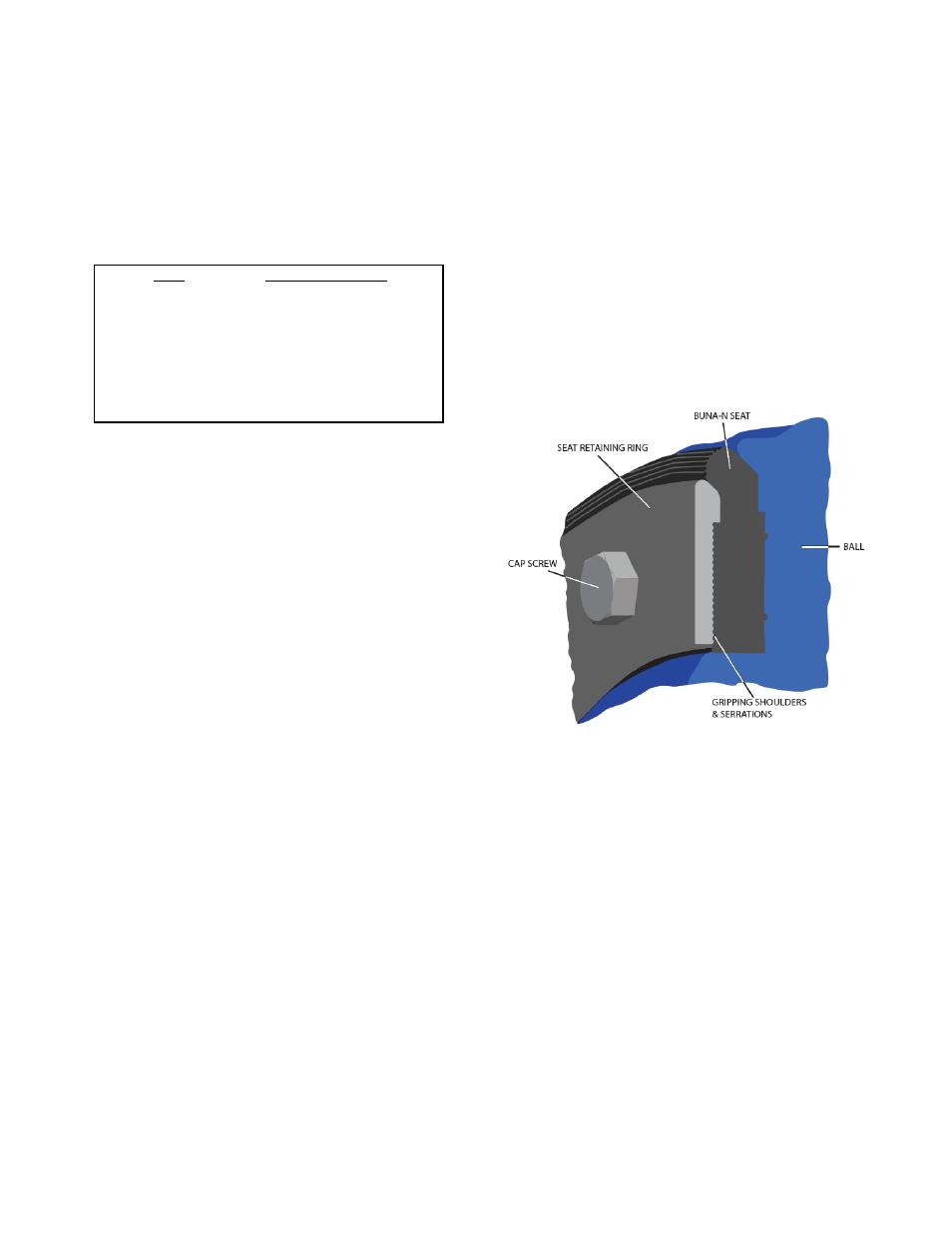
5. Install new seat (6), retaining ring (7) and seat
bolts (8) into ball. Apply thin film of food-grade
grease such as Dow Corning #7 to rubber surface.
Lightly tighten seat bolts until bolt heads touch
body ring.
6. Install thrust bearing cap (15), thrust bearing (18)
and, thrust shims (17) with the o-ring seal (20).
7. Lubricate ID and OD of packing set with food-
grade grease and install in packing bore one ring
at a time taking care to keep lips pointing down
toward valve.
8. Install body o-ring (24) and short body half (1B)
with body bolts (19).
9. With valve fully closed, torque seat bolts in a
cross-over pattern to torque given in Table 4.
10. Insert key (24) into shaft and place actuator over
valve. Reinstall actuator mounting bolts and
torque per Table 7. Install cover on actuator.
Cycle valve. Apply pressure to valve and check
for seat leakage. Tighten seat bolts ½ turn at a
time as necessary.
11. If valve does not shut off tight, adjust the closed
position stops as described on page 6 under
"Closed Position Adjustment". so that ball face is
parallel to body flange within 1/8 in.
FIGURE 9. RUBBER SEAT
SEAT REPLACEMENT
If the seat is badly worn or damaged, gain access to
valve interior and remove existing cap screws, seat
retaining ring, and seat.
1. Clean mating surfaces of body seat, ball and
retaining ring with stiff wire brush in the direction of
the machine grooves.
2. Install new seat (6) onto ball so that the o-ring
bead side is against the disc with the holes
aligned.
3. Start at the top of the ball and install a section of
retaining ring (7) with three new seat bolts (8) and
lightly tighten seat bolts until the bolt heads touch
the retaining ring.
SIZE
TORQUE
(FT-LBS)
1/2"-13
45 - 75
5/8"-11
100 - 150
3/4"-10
150 - 250
7/8"-9
200 - 350
1"-8
300 - 500
1 1/8"-7
450 - 700
1 1/4"-7
650 - 1000