Val-matic’s 1/2”-3” well service air valve, Operation, maintenance and installation, Introduction – Val-Matic 1/2-3 Well Service Air Valve With Dual Port Throttling Device User Manual
Page 2: Receiving and storage
VAL-MATIC’S 1/2”-3” WELL SERVICE AIR VALVE
OPERATION, MAINTENANCE AND INSTALLATION
INTRODUCTION
This manual will provide you with the information
to properly install and maintain the valve to
ensure a long service life. The Well Service Air
Valve has been designed with stainless steel
trim to give years of trouble free operation. The
purpose of the valve is to automatically
discharge and admit air into the discharge pipe
of a vertical turbine or well pump.
The Size, Maximum Working Pressure, and
Model No. are stamped on the nameplate for
reference.
NOTE:
While Well Service Air Valves will
exhaust large quantities of air upon start-up,
they will not continuously release air during
system operation. For that function, a
Combination or Air Release Valve is required in
the piping system.
Also, this valve is not intended for fluids
containing suspended solids such as
wastewater. For wastewater and other high
turbidity applications, use Val-Matic Series 300
Wastewater Air/Vacuum Valves.
RECEIVING AND STORAGE
Inspect valves upon receipt for damage in
shipment. Unload all valves carefully to the
ground without dropping.
Valves should remain boxed, clean and dry until
installed to prevent weather related damage. Do
not expose seat to sunlight or ozone for any
extended period.
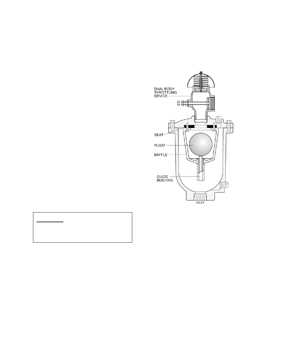
Figure 1. 1/2”-3” Well Service Air Valve
CAUTION:
This valve is not intended
for fluids containing
suspended solids or
hazardous gases.
DESCRIPTION OF OPERATION
The valve is designed to exhaust large
quantities of air upon pump start-up and allow
air to reenter the line upon pump shutdown. As
water enters the valve during startup, the float
will rise and close the outlet port. The exhaust
rate is controlled by the throttling device and
helps reduce surges in the pump column. The
valve will remain closed while the pump is
running.
The only moving parts in the valve are the float
and the float guide. The float guide assures that
the float makes contact with the resilient seat at
the optimum angle.
The external bolt in the throttling device allows
field-adjustable control of the air exhaust rate.
1