Val-Matic 6-8 Combination Air Valve (Single Housing Type) User Manual
Page 2
1
VAL-MATICS 6”-8” COMBINATION AIR VALVE
OPERATION, MAINTENANCE AND INSTALLATION
INTRODUCTION
This manual will provide you with the information
to properly install and maintain the valve to
ensure a long service life. The valve has been
designed with stainless steel trim to give years
of trouble free operation. The Combination Air
Valve is typically mounted at the high points in a
piping system and performs the functions of both
an air release valve and an air/vacuum valve.
The Combination Air Valve automatically vents
air, which accumulates at high points in a
system during its operation. The valve will also
exhaust and admit large quantities (volumes) of
air during filling or draining operations and after
emergency conditions such as a power failure.
Both the air release and air/vacuum functions
are needed to maintain pipeline efficiency while
providing protection from adverse pressure
conditions.
Note: This valve is not intended for fluids
containing suspended solids such as
wastewater. For wastewater and other high
turbidity applications, use Val-Matic Series 800
Wastewater Combination Air Valves.
The valve is a float operated, resilient seated
valve designed to handle clean fluids. The
Maximum Working Pressure, and Model No. are
stamped on the nameplate for reference.
RECEIVING AND STORAGE
Inspect valves upon receipt for damage in
shipment. Handle all valves carefully without
dropping. Valves should remain boxed, clean
and dry until installed to prevent weather related
damage. For long term storage greater than six
months, the valve must remain in the box and
stored indoors. Do no expose valve to sunlight
or ozone for an extended period.
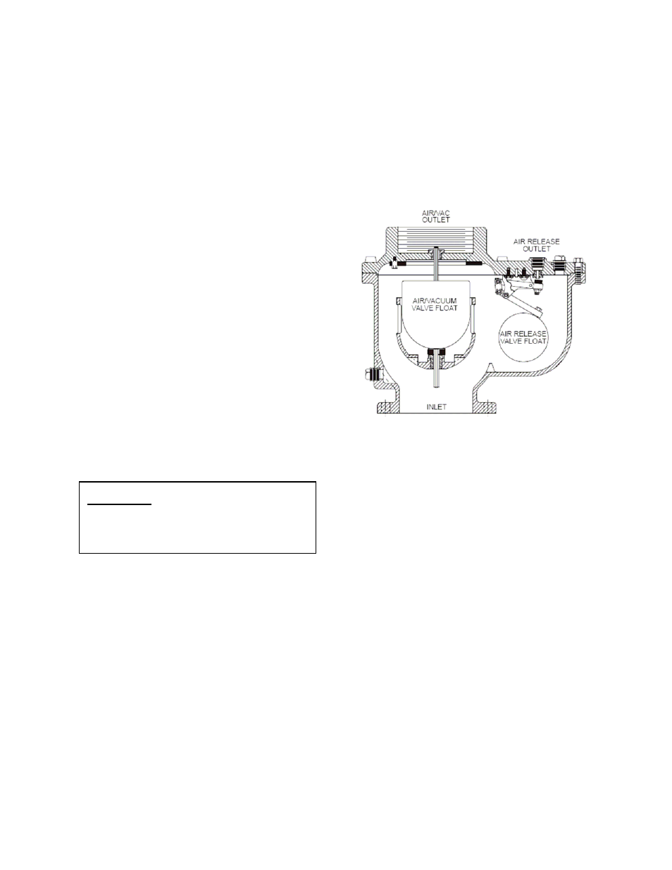
Figure 1. 6”-8” Combination Air Valve
DESCRIPTION OF OPERATION
The Combination Air Valve is fully automatic and
designed to continuously remove air
accumulating at the high points in a piping
system. It also will exhaust and admit air during
filling and draining of the pipeline or tank.
The valve consists of an air/vacuum valve
mechanism with a full size outlet and an air
release valve mechanism with a small diameter
(i.e. 3/8”) precision orifice. The combination air
valve as shown is Figure 1 is a normally open
valve and has three functions as follows.
1. During system startup, the open valve
will exhaust large volumes of air through
the large outlet. When fluid enters the
valve, the air/vacuum float will rise and
seal against the seat. At the same time
the round float will rise and press the
orifice button against the air release
orifice. The air/vacuum float will remain
closed until the pressure drops close to
zero.
CAUTION:
This valve is not intended
for fuel service or fluids
containing suspended
solids.