Maintenance, Wiring diagram, Replacement parts list – Avalon Stoves Freestanding Stove User Manual
Page 32: For qualified service personnel only)
3 2
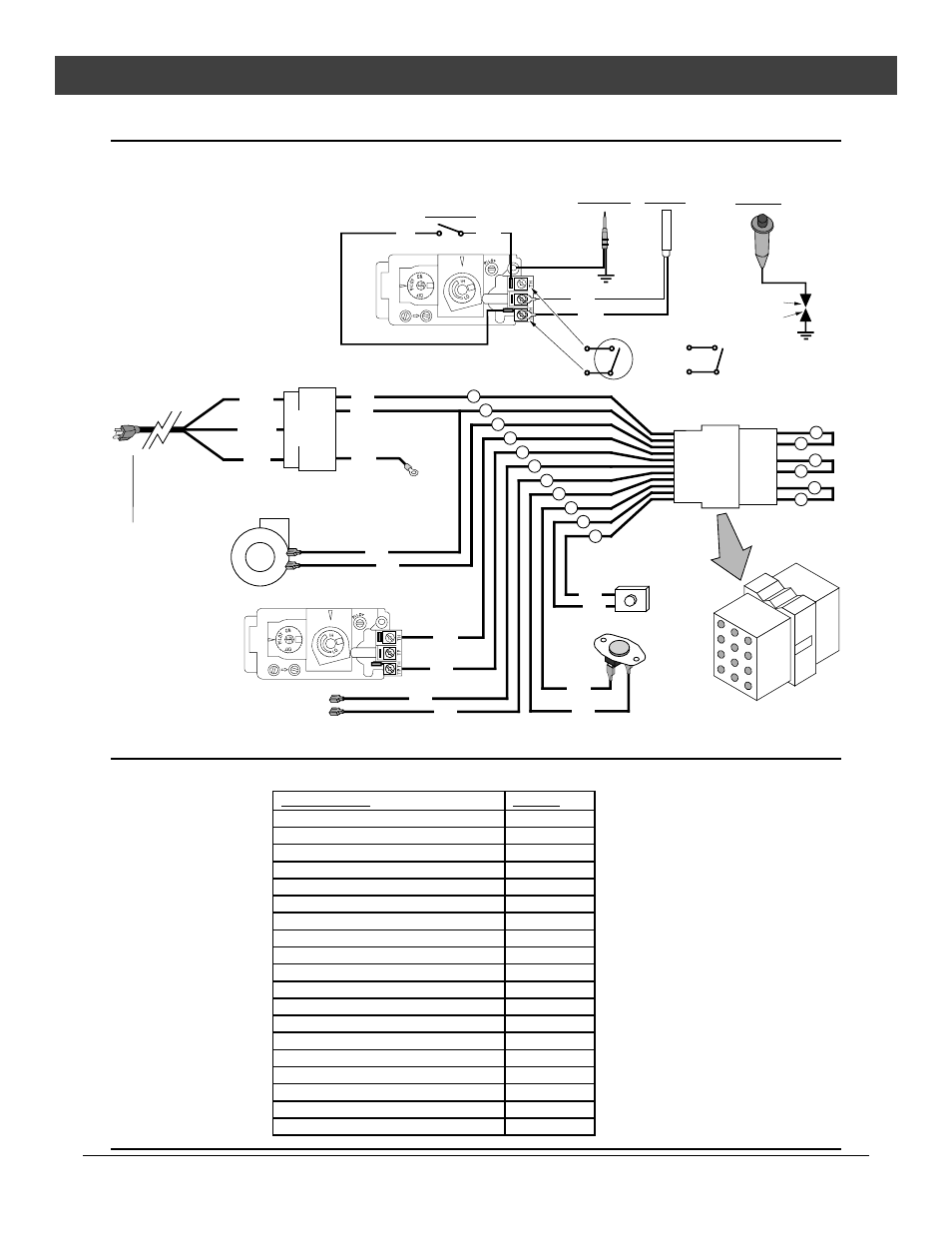
Maintenance
(for qualified service personnel only)
Travis Industries
9 3 5 0 8 1 1 5
4 0 5 0 1 1 3
Wiring Diagram
Caution:
Label all wires prior to disconnection when servicing controls. Wiring errors can cause
improper and dangerous operation.
120 Volt Wiring
Millivolt Wiring
(for gas control valve)
Orange
White
Piezo Igniter
Thermopile
Red
Thermocouple
Copper Co-Axial
Wire
Red
Optional Remote
Control
Spark Electrode
Pilot Hood
On/Off Switch
Brown
Optional
Thermostat
7
4
10
9
1
3
Optional
Blower
Green
Hot
(black)
Common
(white)
Ground
(green)
Blower
Snap Disk
Power In
Molex
Connector
Power Supply
Ground
(attached to stove)
White
Black
1
3
5
7
2
4
6
8
9
12
11
10
3
6
White
9
2
5
Black
Remote
Control
Molex
Connector
8
11
Blue
Blue
Optional Regulator
Solenoid
1
4
Black
Black
7
Black
Black
10
Red
Brown
Rheostat
Gas Control
Valve
Replacement Parts List
Caution:
Use only Travis Industries replacement parts. Do not use substitute materials.
Description
Part #
Air Shutter Assembly
93006512
Air Shutter Control Rod
93006514
Burner Assembly
Burner Mixing Tube
93006511
Control Valve, Natural Gas
93006506
Control Valve, Propane
93006507
Conversion Parts, LP
93006503
Conversion Parts, NG
93006502
Knob, for Rheostat
99300657
Log, Left
93006901
Log, Rear
93006902
Log, Right
93006903
Log Set
93006900
Manual, Prairie
93508115
Piezo Igniter
98900751
Regulator, Natural Gas
93006500
Regulator, Propane
93006501
Rheostat, Blower w/ Off Position
93006504
Wiring Harness
93006505