Reelcraft Series L30000 Cable Reels User Manual
Page 2
Series L 30000 Cable Reels
Page 2
www.reelcraft.com
Inspection
Unpack and inspect reel for damage. Turn the
reel by hand to check for smooth operation.
Check for completeness.
Mounting of all Hose Reels
NOTE: Ensure that mounting surface is flat to
prevent binding on reel after it is mounted.
1. Two 1/2” diameter mounting holes are
located at the base of each side support
panel (2 each). Mount reel using four
(customer supplied) bolts’ tightening them
securely to ensure a solid, rigid
attachment.
Installation Instructions
Ensure that only a qualified electrician install/
services this equipment. Observe
applicable NEC, OSHA, and local codes when
installing this equipment.
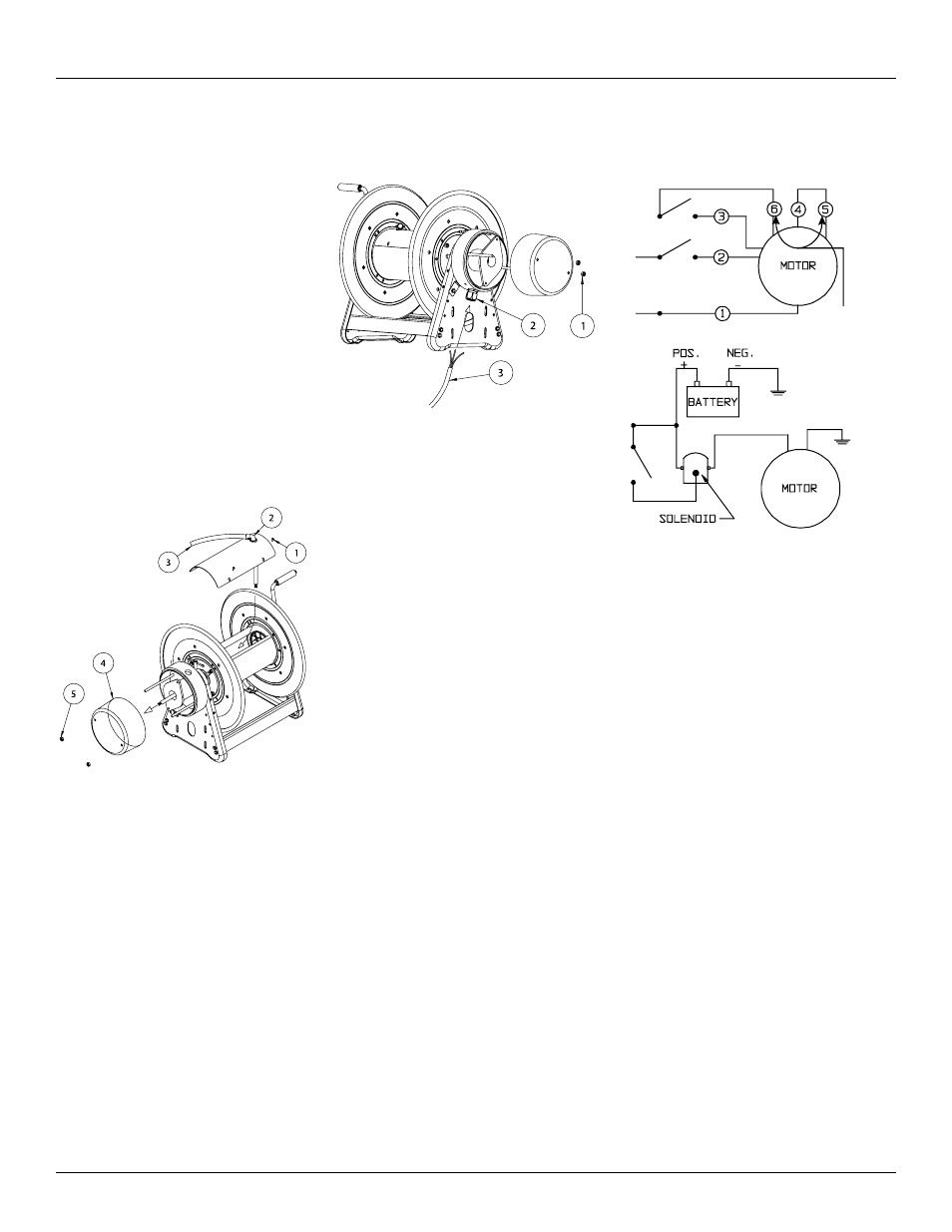
Installing the Output Cable
1. Remove the 4 screws holding spool cover
(1).
2. Loosen screws on 90° strain relief (2) and
feed approximately 18” thru. Tighten
screws.
3. Feed cord thru shaft and replace spool
cover.
4. Connect output wire (3) to collector ring
wire leads per NEC recommendations.
(Not knife disconnects).
5. Replace collector ring cover (4) and tighten
nuts (5).
NOTE: make center harness connections as
short as possible to prevent rubbing on slip
ring cover.
Installing the Inlet Cable
1. Remove the 2 nuts holding collector ring
cover (1).
2. Feed inlet cord thru grommet (2) in
collector ring base approximately 6-8”.
Tighten grommet.
3. Slide protective sleeve over each inlet wire.
4. Attach supplied knife disconnects to inlet
wires (3) & crimp.
5. Make knife connection & slide protective
sleeve over knife connections.
Power Driven Reels
1. Driven which end of reel, motor is to be
mounted on. If the original factory
configuration is not condusive to your
application see section in this manual
titled, “Modifications.”
CAUTION: Remove all electrical power when
wiring. Do not hot-wire. Observe all applicable
NEC/OSHA requirements.
2. Ensure that supply and motor voltage
ratings are compatible.
3. Consult wiring diagrams and determine
which one is applicable to your reel.
4. Perform electrical wiring following
applicable diagram.
Hot
Neutral
SINGLE POLE
SINGLE-THROW
DOUBLE POLE
SINGLE-THROW
SWITCH
Connection shown
gives counter-
clockwise rotation
looking at end of
motor shaft. To
reverse rotation
interchange Leads
5, 6.
12/24 VOLT
D.C.