Reelcraft Series L7000 Spring Driven Cord Reels User Manual
Page 2
Series L 7000 Spring Driven Cord Reels
Page 2
www.reelcraft.com
INSTALLATION INSTRUCTIONS
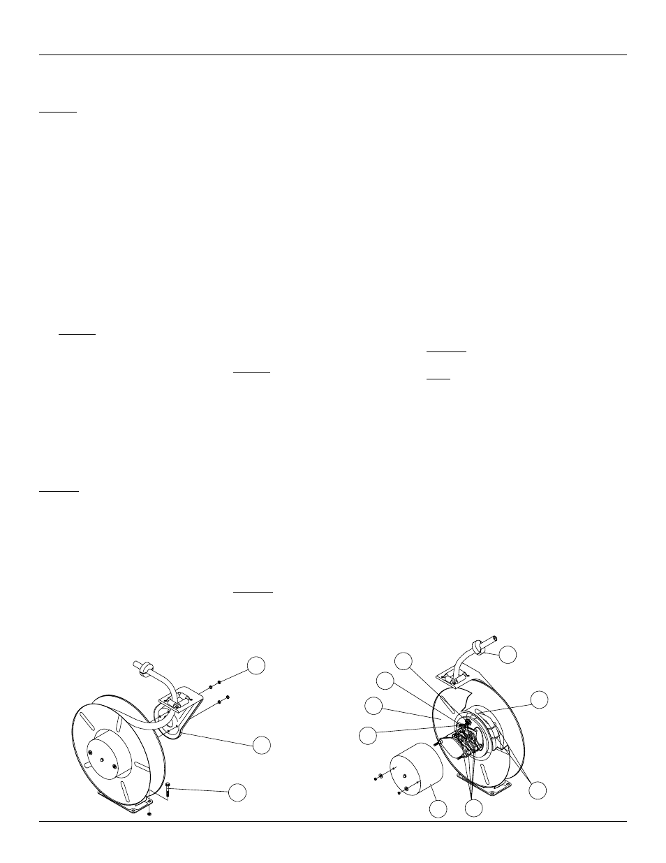
MOUNTING - See Figure 1
Caution: Unless the reel was specified
differently when ordering, maximum
installation height is 16 feet. Do not exceed
this distance. Ensure that only a qualified
electrician installs/services this equipment.
Observe applicable NEC, OSHA, and local
codes when installing this equipment.
1. Unpack and inspect reel for damage.
Turn by hand to check for smooth
operation. Check for completeness.
2. Configure reel for top, side, or
bottom-wind (bottom-wind for constant
tension reels only) electrical cable
dispensing by removing nuts (1)
securing guide arm bracket (2). Position
guide arm bracket to desired location and
replace nuts.
Caution: When changing guide arm
positions, the U-bolt must be placed in
the proper location as instructed in
figure 3 on page 3. The reel can “latch
out” during use if this instruction is not
adhered to.
3. Position reel on floor, wall, or ceiling.
Secure into place using four
(customer supplied) screws or bolts (3).
INSTALLING THE OUTPUT ELECTRICAL
CABLE - See Figure 2
Warning: Select output cable in
accordance with power requirement of
apparatus to be supplied. Ensure that
application does not exceed electrical rating of
reel (see page 3 in this manual).
Use extreme caution; reel under tension. Avoid
releasing latch mechanism.
1. Manually turn sheave (4) until spring is
tight. Back off three turns, then latch.
2. Remove access cover (5).
3. Remove 8” of output electrical cable outer
jacket.
4. Loosen strain relief (6).
5. Route output electrical cable through
U-clamps (7), cutout in spool (8), then
through strain relief (6).
6. Tighten U-clamps (7) and strain relief (6).
7. Using wire nuts (9), connect output elec-
trical cable wires to collector assembly
brush wires as indicated in illustration.
Connect ground wire of output electrical
cable to ground lug (10) located on inner
side of spool.
8. Using ohmmeter, check for ground faults.
9. Install access cover (5).
10. Release latch and wind output electrical
cable onto reel.
11. Install cable bumper (11).
ADJUSTMENTS
SPRING TENSION
If necessary, adjust spring tension on reel by
adding or removing wraps of electrical cable
from spool, one wrap at a time, until desired
tension is obtained. Add wraps to increase
tension. Remove wraps to decrease tension.
Caution: When adding wraps of electrical
cable, be careful not to exceed the wind-
ing mechanism’s spring capacity. Add just
enough wraps of cable to achieve the desired
tension. Damage to the winding mechanism
will result if spring is
over-tensioned. A high-tension spring
assembly is contained within the reel. Exercise
extreme caution.
TROUBLESHOOTING -
See Figure 2
Troubleshooting of the reel consists of
isolating a problem to a defective electrical
cable or collector assembly. Refer any other
discrepancies only to an authorized service
person or directly to Reelcraft.
Warning: The following procedure directs
the technician to take voltage measurements.
Remember, even low voltage is dangerous and
can cause personal injury or death. Exercise
extreme caution!
1. Remove power from reel.
2. Remove access cover (5).
3. Remove wire nuts (9) securing output
electrical cable wires to collector
assembly brush wires. Ensure that
bare wires do not contact each other or
the reel superstructure.
4. Apply power to reel.
5. Using voltmeter, check voltage between
black wire (hot) and white wire (neutral)
then between red wire (hot) and
white wire (neutral). If voltage readings
are correct (120 vac), replace output
power cable (refer to SERVICE
INSTRUCTIONS). If either voltage
reading is incorrect, replace collector
assembly (refer to SERVICE
INSTRUCTIONS).
SERVICE INSTRUCTIONS
Warning: Remove power from reel before
performing the following procedures.
Note: Refer all repairs for the collector ring
assembly to the factory.
REPLACING THE OUTPUT ELECTRICAL
CABLE
-
See Figure 2
Warning: Use extreme caution; reel under
tension. Avoid releasing latch mechanism.
1. Pull output electrical cable from reel until
cable is fully extended, then latch.
2. Remove wire nuts (9) securing output
electrical cable wires to collector assem-
bly brush wires.
3. Remove output electrical cable ground
wire (12) from ground lug (10).
4. Loosen strain relief (6).
5. Loosen U-clamps (7).
6. Remove output electrical cable.
7. Remove cable bumper (11).
8. Install replacement output electrical cable
(refer to INSTALLATION INSTRUCTIONS).
4
6
10
5
9
7
8
11
Figure 2
1
2
3
Figure 1
12