Installation and mechanical set-up, Rapid master installation, Mechanical set-up of die or punch – Rapid-Air AIR FEED / RAPID MASTER WITH KEYPAD User Manual
Page 3
The Rapid Master that you have just re-
ceived is fully assembled and ready to
be put into production. Due to shipment
vibration and handling, the machine
should be checked to ensure all screws
and bolts are tight. Remove the cover
to the electrical controls and visually
inspect that all parts are in place and
secure. If the machine was damaged
in shipment, contact the carrier first to
report the damage and then Rapid-Air.
CAUTION:
THE RAPID MASTER MACHINE IS TOP
HEAVY WHEN NOT SITTING ON ITS
BASE LEGS. USE EXTREME CAUTION
WHEN MOVING THIS MACHINE!
installation and mechanical set-up
rapid Master Installation
1) The customer must provide
minimum CFM – RE: chart, at 75
o 120 PSI of dry air to the machine.
Connect a minimum of 5/8” ID hose
into the filter regulator provided on
the machine. The inlet to the F-R-L
is a NPT female thread.
2) The customer must provide 120
volt, 20 amp, 60 cycle electrical
power. If an extension cord is
used between the source and the
machine, it should be a minimum
12 gauge wire to keep the voltage
loss down and for electrical
safety reasons.
Install machine on a level surface
with sufficient clearance for loading
and unloading process material.
The machine should be secured
to the floor through the 4 holes
provided in the feed of the machine
using 7/16 tie-down bolts. Or, can
be installed using 1/2-13 leveling
bolts and machine pads. The pads
keep the machine from walking
during operation and also act as a
noise reduction device.
The machine has two other
requirements that need attention
before putting the Rapid Master
into production.
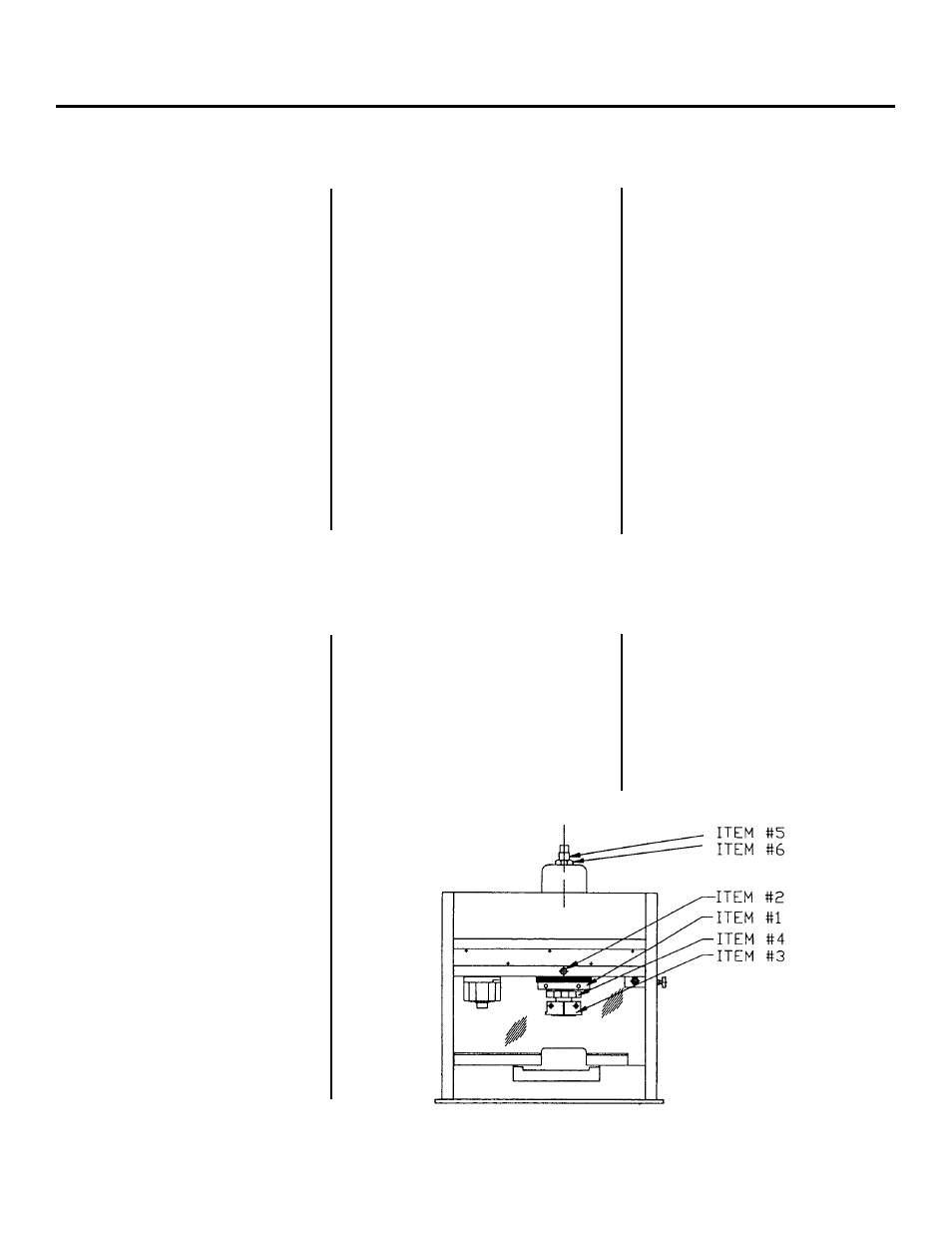
1) Secure the die set to the
bolster plate.
2) The piston adjustment sleeve
(item #1) establishes the stroke to
a maximum of .50 inches when
fully extended. The stroke is
reduced by 1.8 inches with each
full inward rotation, using the 3-3/4
spanner wrench provided. The
piston stroke adjustment sleeve is
locked in place with a nylon tipped
set screw (item #2).
3) Lift the punch holder plate and
loosely connect it to the inner shaft
ram adjustment screw with the
two half shell clamps (item #3)
provided.
4) Adjust the inner shaft (item #4) for
proper open height, using the
wrench provided.
5) Tightly secure the punch holder
plate to the inner shaft.
6) Lower the piston, piston shaft and
piston sleeve by rotating the
adjustment screw on top of the
head assembly (item #5) with the
crank provided. This is done to
check the full stroke set up. If all
adjustments are within limits, the
top adjustment screw should be
retracted to fully raise the piston
and ram assembly.
7) Lock the upper adjustment screw
(item #6) in the up position.
Mechanical Set-Up Of Die Or punch