Pumptec 114T SERIES User Manual
Page 7
7
Version 012313
Pumptec Operating Instructions and Parts Manual
PUMP SERIES 114T
MAINteNANce
DISASSEMblY AnD REASSEMblY
InSTRUCTIOnS (Refer to Schematic)
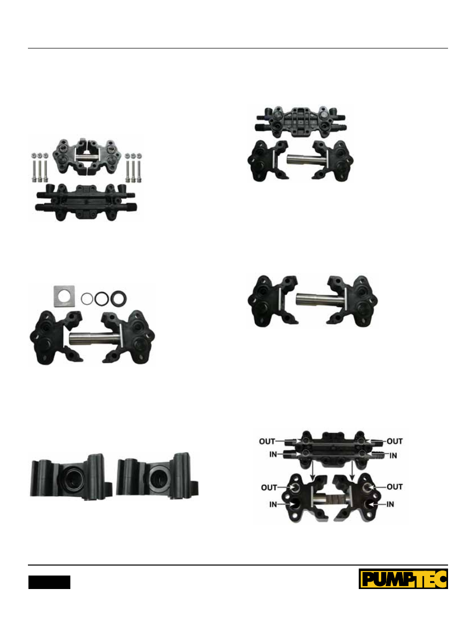
1. Remove pump from motor using a 3/16” hex wrench.
Remove remaining bolts from manifold of pump. Place
Manifold to side as a reference for re-assembly.
Figure 1
2. Holding each head, pull them apart to remove plunger.
Remove retaining plate from pump head. Remove internal seal
parts with finger. Discard parts.
Figure 2
3. Clean the head with a rag or towel. Inspect for damage or
excess corrosion. If the head is damaged, do not rebuild. note
the order and orientation of repair parts prior to installation.
4. Place o-ring around seal ring and gently place them into seal
bore.
Figure 3
5.
Place guide into seal bore, level above the o-ring seal
assembly. Apply even downward pressure to guide to install
seal and guide into seal bore. Remove guide and verify that
o-ring and seal are properly installed without bulges or
creasing. Slide the retaining plate back into place.
Figure 4
6. Repeat the previous steps 3-5 with the other head.
7. lightly grease the plunger with provided grease in small grey
tube. Slide plunger into one head assembly and then slide the
other head onto plunger. Place head and plunger assembly on
work surface with valves facing upward.
Figure 5
8. Adjust plunger slot position towards center and have slot
facing work surface. Replace all valves and o-rings that may
have fallen out during repair. Refer to image and manifold label
to understand proper orientation.
IMPortANt:
It is imparative the alignment of OUT/In
ports coincide with valves as indicated in Figure 6.
Figure 6