Powermate 024-0181CT User Manual
Page 5
5 - ENG
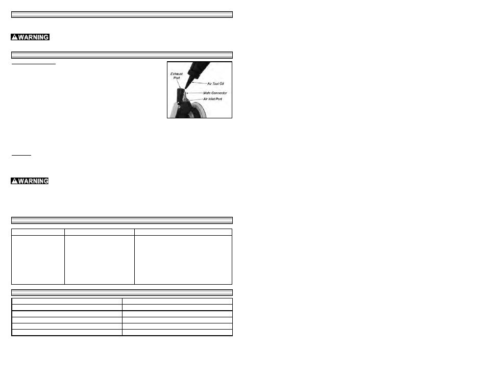
Air Motor Lubrication
To maintain the maximum performance of the air tool, it must be lubricated
each time it is used. Dust, dirt, rust and oil residue will build up inside the tool
and reduce the performance. An in-line oiler is recommended for proper
automatic tool lubrication (see Figure 1). If an in-line oiler is not available, the
tool can be lubricated manually through the inlet port (see Figure 4).
1.
Disconnect the air tool from the air supply.
2.
Remove the hose and dust bag from the tool.
3.
Turn the tool sideways and while depressing the throttle, add 4-6 drops of
Coleman Powermate® air tool oil #018-0059SP or SAE10 nondetergent oil
into the air inlet. NOTE: Depressing the throttle helps circulate the oil in
the air motor.
4.
Reconnect the tool to the air supply, cover the exhaust port end with a towel and run for approximately 30
seconds to remove excess oil.
NOTE: If the tool remains sluggish after it has been lubricated, the internal components may need to
be cleaned.
To Clean:
Disconnect the air tool from the air supply and pour or spray a generous amount of WD-40® into the air inlet
with the throttle depressed. Connect the tool to the air supply, cover the exhaust port end with a towel and run for
approximately 30 seconds. Follow the air motor lubrication instructions above after cleaning is completed to re-
lubricate the tool. NOTE: Do not use solvents when cleaning plastic parts.
After oiling or cleaning, cover the exhaust port with a towel and operate the tool for a
few seconds to safely remove the excess oil. Clean the handle and surface of the tool
of any oil residue. Failure to cover the exhaust port and clean the tool, can
result in serious injury. Note: Keep the towel away from moving parts!
NOTE: Do not use solvents such as brake fluids, gasoline, thinner, etc., when cleaning
plastic parts on this tool. This could damage or destroy the tool.
USER-MAINTENANCE INSTRUCTIONS
USER-MAINTENANCE INSTRUCTIONS
TROUBLESHOOTING GUIDE
TROUBLESHOOTING GUIDE
Figure 4
T
T
OOL
OOL
SPECIFICA
SPECIFICA
TIONS
TIONS
Air Inlet
1/4” NPT (Female)
Average SCFM Requirements
9.0 SCFM @ 90 PSI
Recommended Hose Size
3/8”
Maximum Working Pressure
90 PSI
Maximum RPM
10,000
Sanding Pad Diameter
6”
SYMPTOM
POSSIBLE CAUSE(S)
CORRECTIVE ACTION
Tool will not run or runs
slowly
Grit in tool; tool gummed up
No oil in tool
Low air pressure
Air hose leaks
Clean the air motor inside the tool with WD-40®
(see “user maintenance” section).
Add 4-6 drops of air tool oil into the air inlet of the
tool (see “user maintenance” section).
Adjust compressor regulator to 90 PSI.
Tighten and seal hose fittings with Teflon® tape if
leaks are found.
NOTE: Proper sanding requires starting with sandpaper just course enough to remove the high spots and
surface roughness and changing to successively finer sandpaper until the desired surface finish is achieved.
Always disconnect the tool from the air source before changing sandpaper pads. Do
not operate the tool if the sanding pad is not tightened to the sander.
OPERA
OPERA
TING INSTRUCTIONS
TING INSTRUCTIONS