F830-4 unit, F800, Humidifier installation – Paasche Airbrush F830-4 User Manual
Page 2: Paasche, Series automatic humidifier page 2
PAASCHE
F800
- Series Automatic Humidifier
Page 2
The F800- Series Automatic Humidifier Units will automatically dispense gallons of finely atomized water, providing controlled humidity
when the dial on the humidistat (Item #1) is adjusted to the humidity required. These Automatic Humidifier Units will automatically start and
stop at the humidity setting. When properly connected to the water and electric systems of the building and to an air source that supplies
constant air pressure (minimum 50 p.s.i.) to the F800 Series Unit, these units will deliver finely atomized water for extended periods.
HUMIDIFIER INSTALLATION
1. Mount Humidifier Unit in convenient location using SM-42 Mounting Bracket (not
shown).
2. Connect air supply to HF-1/4" Air Inlet Valve.
3. Connect water supply to HF-1/4" Water Inlet Valve.
4. Open air inlet valve and water supply valve under air supply valve check for leaks.
Tighten connections if required.
5. Turn humidistat control dial on item #1 counterclockwise to off position before plugging
cord into grounded outlet.
6. Turn U-3178 Fluid Adjusting Knob on back of Spray Guns to closed position by turning
clockwise -Do Not Over Tighten. Set “0” on reference dial to line up with “0” on fluid adjusting
knob and then open adjusting knob to number 30.
7. Set Regulator item #7, located behind Gauge #2, at 50 p.s.i. minimum air pressure (60
p.s.i. maximum).
8. Plug units three wire electrical plug into properly grounded receptacle (115V., 60cy).
9. Turn Humidistat control dial to on position and desired humidity. You will hear a “click”
when activated.
10. Water flow rate may be adjusted using the U-3178 Fluid Adjusting Knob on back of
each Spray Gun. Mist should always be absorbed into the surrounding air without
settling out onto the floor under the unit.
CAUTION:
DO NOT AIM DIRECTLY AT
CEILING, WALL, MERCHANDISE OR MACHINERY.
SAFETY NOTE:
Do Not allow water vapor to condense or leaks to drip onto floor or
unit, if this condition exists, check for:
a. Water leaks from connections or Spray Gun nozzles.
b. Insufficient atomization. Correct by increasing air pressure and/or decreasing fluid flow.
c. Humidistat setting too high. Lower setting if necessary.
d. Open drain valve on R-75AR Regulator/Condenser item #7 periodically to drain airline
moisture buildup.
CAUTION:
Guard Face and Eyes so escaping air and moisture do not cause injury.
WARNING:
Humidifier must never be used to create a fog condition in which water
may collect on the unit and produce an electrical hazard.
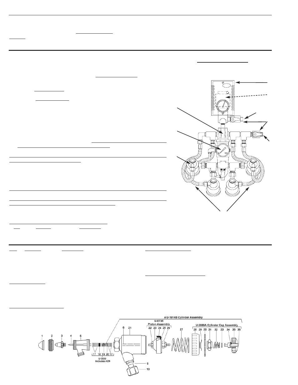
MAJOR COMPONENTS FOR F800-SERIES HUMIDIFIERS
No.
Part No.
Description
1.
845
Humidistat
2.
GB-1-1/2"-100#
Air Pressure Gauge
3.
AB-H-AUR-1
Humidifier Spray Gun (Drawing below)
F830-4 UNIT
Air Inlet
1
2
3
4
7
6
5
Water
Inlet
No.
Part No.
Description
1.
AR-15-1
Aircap
2.
AU-12
Aircap Nut
3.
AU-1
Tip
4.
A-AU-3-11/16
Needle
5.
AU-7B
Fluid Body
9.
U-1432A
Ball Stud
10.
U-1399
Swivel Nut
U-3502 Packing Set
17.
U-28-12
Packing Washers (12)
18.
U-29
Packing Gland (1)
19.
DU-30
Stainless St. Spring (1)
20.
U-203
Gland (1)
24.
U-322
Cup Leather (1)
AU-1914B Cylinder Assembly
(Note: The AU-1914B includes U-873E & U-2686A)
4.
A-AU-3-11/16
Needle
17.
U-28-12
Packing Washers (3)
20.
U-203
Gland
21.
U-1907B
Shell Assembly
27.
U-2966
Piston Spring
4.
HL-3/16-12IN
Water Hose W/Cplgs.
5.
SM-880
Solenoid Valve
6.
HF-1/4
Valve Assembly
7.
R-76
Air Regulator/Condenser
U-873E Piston Assembly
22.
U-2965
Needle Chuck
23.
U-2964
Inner Bushing
24.
U-322
Cup Leather
25.
U-2465A
Outer Disc
26.
U-2544
Locknut
U-2686A Cylinder Cap Assembly
28.
U-2707A
Cylinder Cap
29.
U-941
Spring Washer
30.
U-951B
Fluid Dial
31.
U-2675A
Friction Nut
32.
U-1098
Spring
33.
U-2584P
Stop Washer
34.
59-57
Lock Stud
35.
U-3178
Fluid Adjusting Knob (Don’t over tighten)
36.
59-56
Lock Screw
behind 845