Amplifier on delay function (cn19), Atx power connector, Battery low led connector – IEI Integration IDDV-6304140A User Manual
Page 4: Cn19), Burner program for microchip, Cn5), Input power connectors, Cn15, cn16, cn17), Infrared interface connector (optional) (cn22), Power on/off switch connector (external) (cn20)
IDDV-6304140A QIG IEI Technology Corp. Page 4
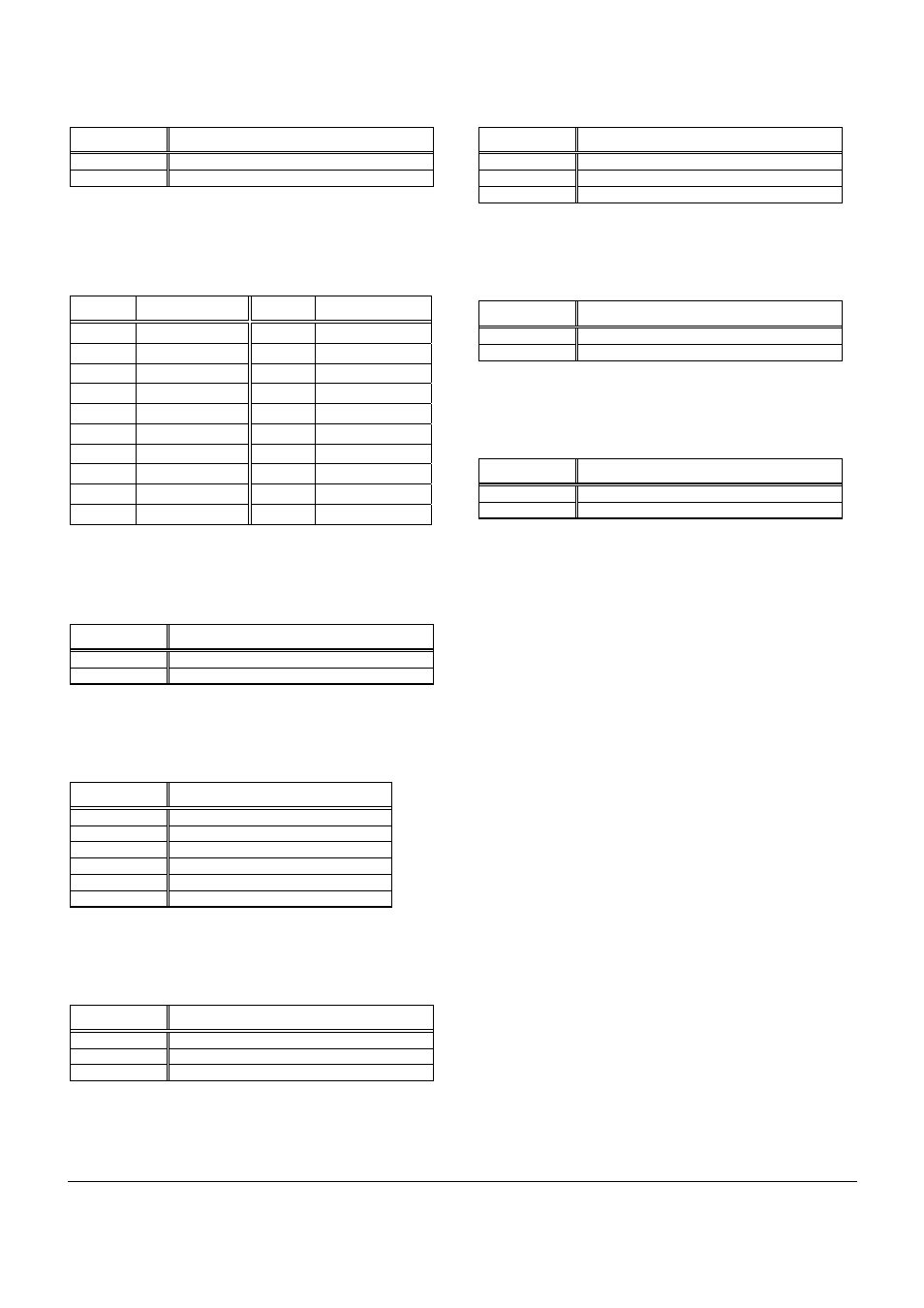
AMPLIFIER ON DELAY FUNCTION
(CN19)
PIN NO.
DESCRIPTION
3 AMP
4 GROUND
Table 2: Amplifier On Delay Function Connector Pinouts
ATX POWER CONNECTOR
(J1)
PIN NO.
DESCRIPTION
PIN NO.
DESCRIPTION
1 3.3V
11
3.3V
2 3.3V
12
-12V
3 GND
13
GND
4 +5V
14
PS_ON
5 GND
15
GND
6 +5V
16
GND
7 GND
17
GND
8 Power
good
18
-5V
9 5VSB
19
+5V
10 +12V
20 +5V
Table 3: ATX Power Connector Pinouts
BATTERY LOW LED CONNECTOR
(CN19)
PIN NO.
DESCRIPTION
1 LEDA
2 LEDB
Table 4: Battery Low LED Connector Pinouts
BURNER PROGRAM FOR MICROCHIP
(CN5)
PIN NO.
DESCRIPTION
1 MODEDD/MCLR
2 Vcc
3 GROUND
4 LED/RB7
5 AMPLIFTER/RB6
6 NC
Table 5: Burner Program for Microchip Connector Pinouts
INPUT POWER CONNECTORS
(CN15, CN16, CN17)
Connector DESCRIPTION
CN15 Battery(+)
CN16
ACC On (signal) (Ignition)
CN17 Battery(-)
(GND)
Table 6: Input Power Connector Pinouts
INFRARED INTERFACE CONNECTOR
(OPTIONAL) (CN22)
PIN NO.
DESCRIPTION
1 GROUND
2 Vcc
(P5V)
3 IRRX
Table 7: Infrared Interface Connector Pinouts
POWER ON/OFF SWITCH CONNECTOR
(EXTERNAL) (CN20)
PIN NO.
DESCRIPTION
1 PWRSW
2 GROUND
Table 8: Power On/Off Switch (External) Connector Pinouts
POWER ON/OFF SWITCH CONNECTOR
(MOTHERBOARD) (CN21)
PIN NO.
DESCRIPTION
1 MB_SW
2 MB_SW1
Table 9: Power On/Off Switch (Motherboard) Connector Pinouts