Figure 3-23: serial device connector, Figure 3-24: serial port pinouts, Table 3-1: rs-232 serial port pinouts – IEI Integration ICECARE 7 User Manual
Page 44: Icecare-07 mobile field assistant page 33
ICECARE-07 Mobile Field Assistant
Page 33
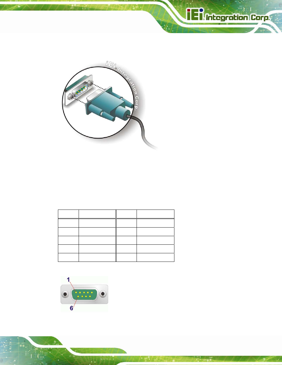
Step 1:
Insert the serial connector
.
Insert the DB-9 connector of a serial device into
the DB-9 connector of the docking cradle. See
44
Figure 3-23: Serial Device Connector
Step 2:
Secure the connector
. Secure the serial device connector to the external
interface by tightening the two retention screws on either side of the connector.
Step 0:
The RS-232 serial port pinouts are shown in the following table.
Pin Description Pin Description
1 DCD
6 DSR
2 RX
7 RTS
3 TX
8 CTS
4 DTR
9 RI
5 GND
Table 3-1: RS-232 Serial Port Pinouts
Figure 3-24: Serial Port Pinouts